
Cellular channel allocation scheme with multi-user detection

Active Publication Date: 2005-02-17
INMARSAT GLOBAL
View PDF22 Cites 43 Cited by
  • Summary
  • Abstract
  • Description
  • Claims
  • Application Information

AI Technical Summary

Benefits of technology

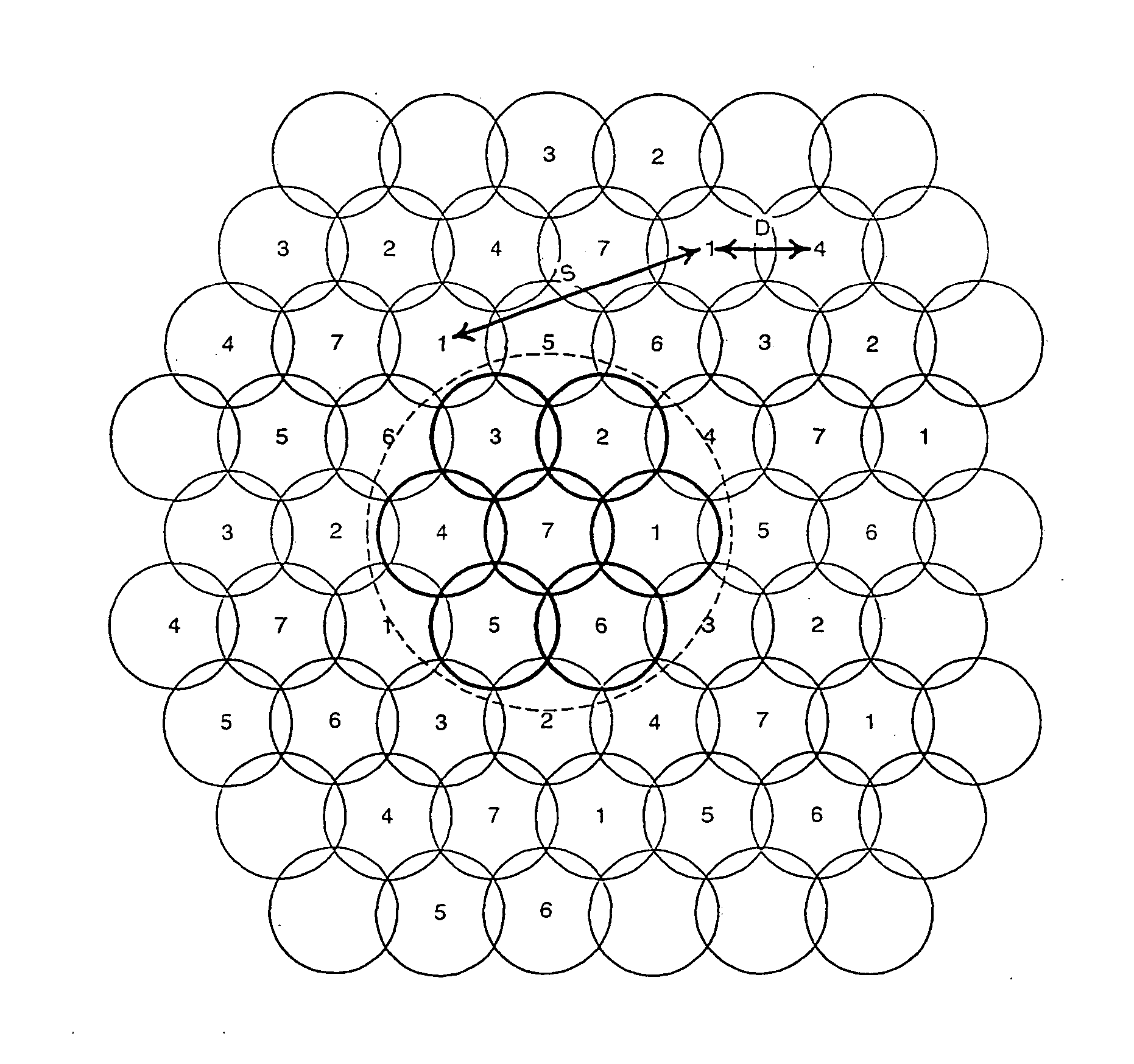
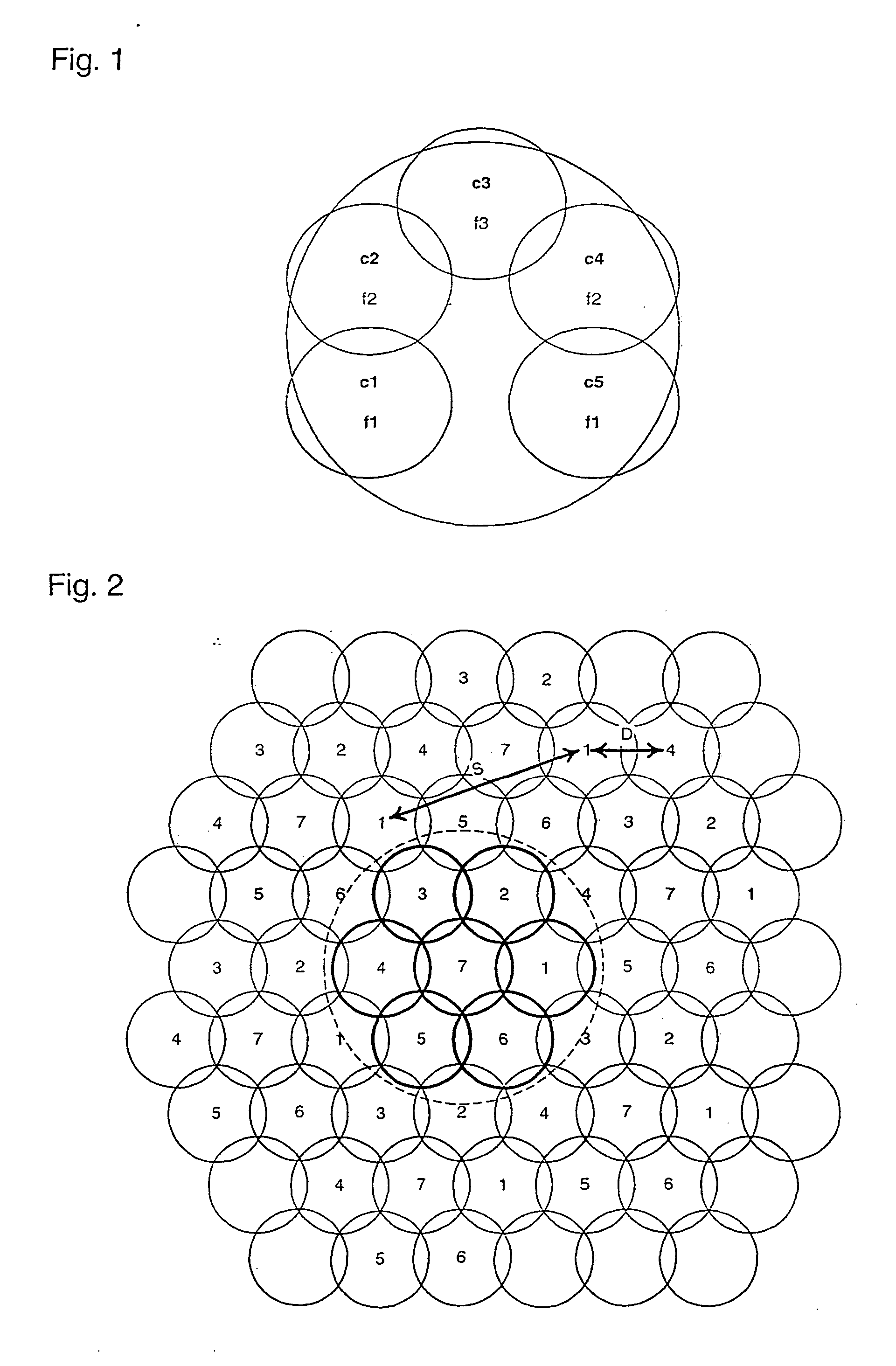
[0021] This clustering arrangement allows a significantly higher reuse factor than the traditional method of allocating bearers to individual cells and reusing bearers between individual cells having sufficiently high mutual isolation.
[0023] Preferably, the user terminals may receive relative timing and / or position information and adjust the timing of their transmissions so as to synchronise their transmissions to a reference timing at a receiver. This allows initial access time slots to be shortened.

Problems solved by technology

The spectrum allocated to Mobile Satellite Service (MSS) is a limited resource and needs to be shared among competing satellite system operators.
In order to accommodate both considerations the MSS satellite designs have become progressively more complex, utilising a large number of spot beams, effectively overlaying the satellite coverage area with a large array of cells on the ground.
Access through this channel is also subject to probability of collisions between competing packets trying to use the same time slot for initial access.

Method used


Image

  • Cellular channel allocation scheme with multi-user detection
  • Cellular channel allocation scheme with multi-user detection
  • Cellular channel allocation scheme with multi-user detection

Examples


first embodiment

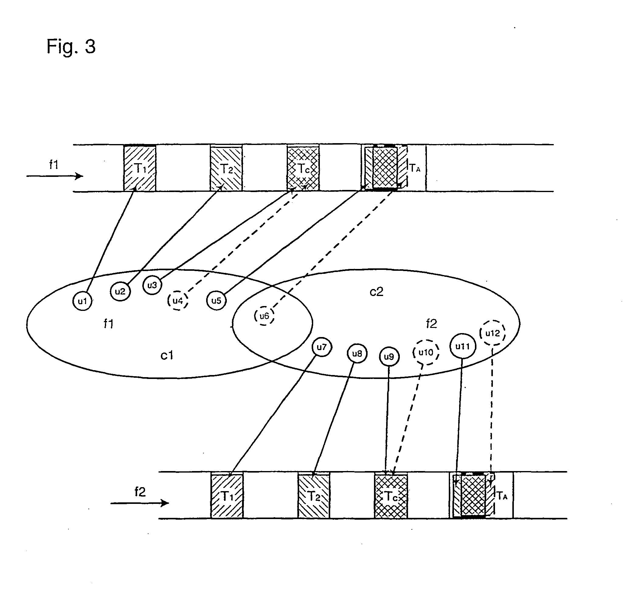
[0034]FIG. 6 shows allocation of time slots to user terminals at frequencies f1 and f2 of a frequency pool shared within a two-cell cluster C in the present invention. The time slots include uniquely assigned time slots T1 and T2, contention-based time slots Tc and initial access time slots Ta. User terminals u1 and u2 in cell c1 are allocated slot T1 at frequencies f1 and f) respectively. User terminals u3 and u4 are allocated the contention time slot Tc at frequencies f1 and f2 respectively. User terminals u5 and u6 attempt initial access in the initial access slot Ta in frequencies f1 and f2 respectively. Likewise, user terminals u7 to u12 use exclusive, contention-based and initial time slots at the frequencies f1 and f2.

[0035] As well as giving improved frequency reuse, the sharing of a pool of frequencies within a cluster gives greater flexibility in the loading of each bearer according to capacity demand from all the user terminals in the cluster, rather than from user termin...

second embodiment

[0038] A greater improvement in the efficiency of spectrum use is obtained in the present invention, in which return link time slots in each bearer may be simultaneously assigned to one user terminal in each cell of a cluster. If there are n cells per cluster, each time slot of each shared bearer may support up to n simultaneous users. A receiver of the transmissions in each time slot receives a signal from each cell, each signal comprising up to n overlapping transmissions. Using the differences between the signals received from the different cells and applying multi-user detection techniques, the receiver separates and decodes each of the overlapping signals. Successful separation and decoding of the overlapping signals requires that the receiver is capable of separating the necessary number it of overlapping signals.

[0039] The technique of the second embodiment is applicable to unique timeslot allocation, except that the time slot is only exclusively assigned to a user terminal t...


PUM


Abstract

In a spectrum allocation method in a cellular communication system, a cell pattern is divided into clusters each containing a plurality of adjacent cells. A pool of forward and return link bearers is allocated to each cluster and may be shared among cells within the cluster. Bearers are reused between blusters having a sufficiently high mutual isolation. Preferably, the same time slot in a return link bearer is allocated to multiple users within the cluster. The receiver of the shared return link bearer uses multi-user detection techniques to separately decode the signals from each user sharing a time slot, using the spatial diversity of the individual cells.

Description

FIELD OF THE INVENTION [0001] The present invention relates to a method and apparatus for spectrum allocation and channel reception in a cellular mobile communications system. BACKGROUND OF THE INVENTION [0002] Maximising spectrum utilisation has been a prime goal in the design of modern mobile satellite systems in recent years. The spectrum allocated to Mobile Satellite Service (MSS) is a limited resource and needs to be shared among competing satellite system operators. Therefore maximising spectrum utilisation and frequency reuse have become a major consideration in the design of modern MSS constellations. Another major consideration is dimensioning of user terminals, with a drive for progressively smaller and more compact terminals. [0003] In order to accommodate both considerations the MSS satellite designs have become progressively more complex, utilising a large number of spot beams, effectively overlaying the satellite coverage area with a large array of cells on the ground....

Claims


Application Information

Patent Timeline
IPC IPC(8): H04W16/00H04W16/12
CPCH04W16/00H04W84/06H04W72/04H04W16/12
Inventor TRACHTMAN, EYAL
Owner INMARSAT GLOBAL
Learn More