Retracting device for a safety syringe

Inactive Publication Date: 2005-02-17
LEE TUN CHI +1
View PDF9 Cites 23 Cited by
  • Summary
  • Abstract
  • Description
  • Claims
  • Application Information

AI Technical Summary

Benefits of technology

[0015] The primary objective of the present invention is to provide an improved retracting device for a safety syringe so that t

Problems solved by technology

However, problems often happen to the users when trying to dispose of the syringe of this type.
Under such a situation, the patient might feel very uncomfortable.
However, because the hook (18) is normally made of metal and metal is not compatible with the glue (19) inside the recess (16) such that when the hook (18) is employed to retract the needl

Method used


Image

  • Retracting device for a safety syringe
  • Retracting device for a safety syringe
  • Retracting device for a safety syringe

Examples


Embodiment Construction

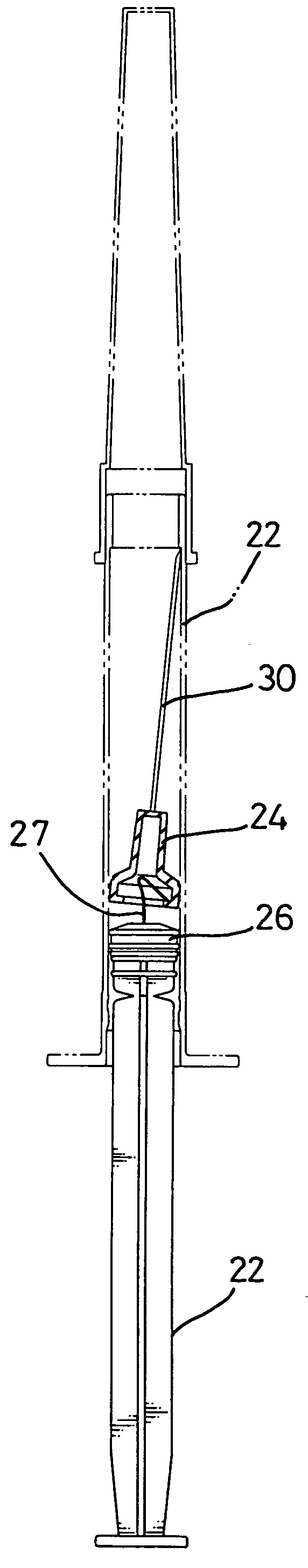
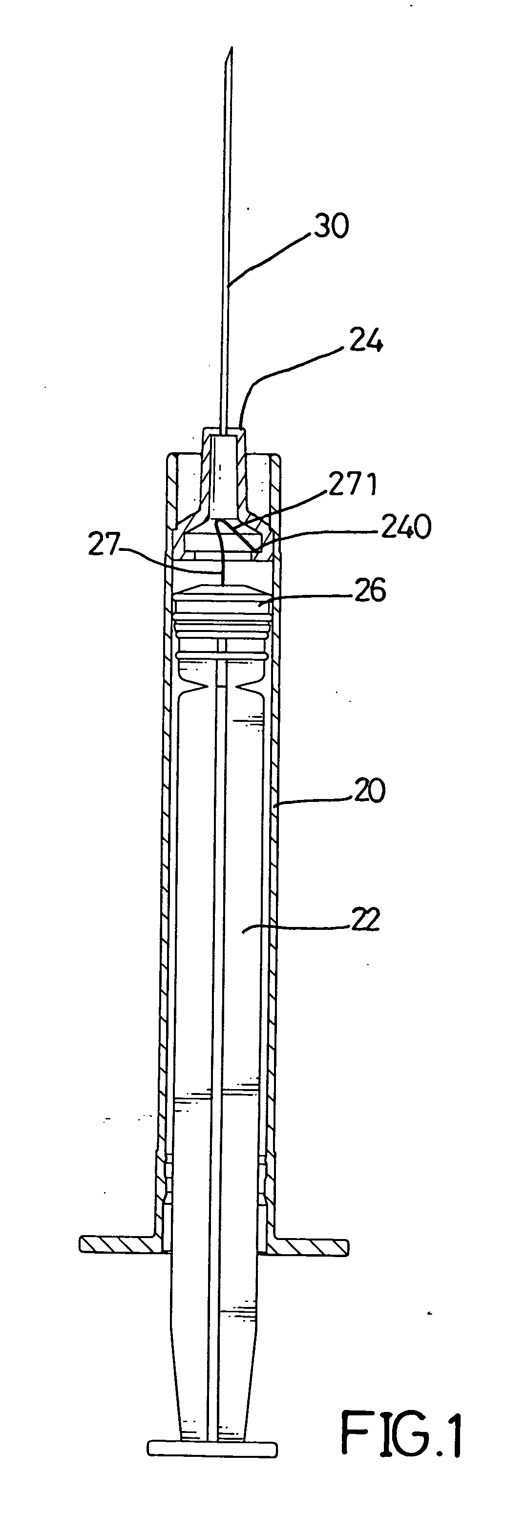
[0031] With reference to FIGS. 1 to 5, the safety syringe in accordance with the present invention has a barrel (20), a plunger (22), a stop (26) and a needle hub (24) with a needle (30) securely and fixedly extending out therefrom and an annular shoulder (240) defined in an inner periphery of the needle hub (24).

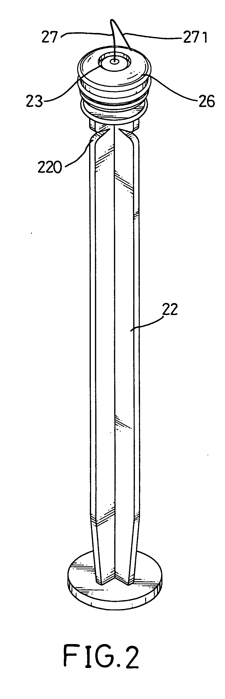
[0032] The plunger (22) is movably received in the barrel (20) and has an assembly seat (23) formed on a distal end of the plunger (22) and having a centrally defined recess (25) defined in the assembly seat (25), wherein the recess (25) has a threading (250) defined in an inner periphery defining the recess (25).

[0033] The stop (26) is to be mounted around the assembly seat (23) to function as a seal while the plunger (22) is received in the barrel (20). That is, the stop (26) engages with an inner periphery of the barrel (20) when the plunger (22) is moved inside the barrel (20).

[0034] A hook (27) is to be mounted in the recess (25) and has a head (270) formed on a fir...


PUM


Abstract

A safety syringe has a barrel, a needle hub movably received in the barrel and having an annular shoulder formed on an inner periphery of the needle hub and a needle extending out from the needle hub. When a hook engages with the annular shoulder and the plunger is moving forward, the stop and the needle hub are free of engagement with one another and thus the needle is slanted relative to the plunger for destruction of the needle.

Description

CROSS REFERENCE [0001] This application is a continuation-in-part (CIP) of co-pending application of Ser. No. 10 / 224,482 filed by the same applicant of this application on Aug. 21, 2002. The content thereof is hereinafter incorporated for reference.BACKGROUND OF THE INVENTION [0002] 1. Field of the Invention [0003] The present invention relates to a retracting device for a safety syringe, and more particularly to a retracting device which is able to satisfactorily pull the needle hub back into the barrel so that the syringe is able to be safely disposed. [0004] 2. Description of Related Art [0005] With reference to FIG. 8, a conventional safety syringe is shown to have a barrel (5), a needle hub (6) and a plunger (7). [0006] The barrel (5) has a step (51) formed on an inner face thereof. The needle hub (6) has a flange (61) corresponding to the step (51) and having a diameter slightly larger than a diameter of the step (51). The plunger (7) has a stop (71) and a hook (72) formed on ...

Claims


Application Information

Patent Timeline
IPC IPC(8): A61M5/32
CPCA61M2005/3249A61M5/322
Inventor SHEN, TINGCHANG, SU-MING
Owner LEE TUN CHI
Why Eureka
Try Eureka