In-operation test of a signal path

Active Publication Date: 2005-02-17
INFINEON TECH AG
View PDF4 Cites 54 Cited by
  • Summary
  • Abstract
  • Description
  • Claims
  • Application Information

AI Technical Summary

Benefits of technology

[0017] The particular advantage of the present invention is that it enables subjecting the overall signal path from a sensor cell to an evaluation location to a continuous self-test without interrupting the measurement or corrupting the measurement value of the sensor.
[0018] As no physical effect is used to generate the test signal, the usability of the inventive test method is not restricted to special cases in which the physical effects may be caused by electric stimulation. In addition, no high powers as for the thermal stimulation of a sensor or high voltages as for the electrostatic generation of forces are required. A crosstalk of test signals from an input to an output of the test chain, as may be caused by energy-rich signals for an e

Problems solved by technology

This means that during the time in which the self-test is performed the sensor device is not operational.
In particular in such security-relevant applications is it disadvantageous if the sensor device is not operational during the self-test.
This offers the advantage of also testing the sensor, is, however, due to the generally high current consumption for obtaining the heating power or due to the enormous voltages for a deflection of a membrane by electrostatics often not acceptable.
In addition, in this method due to the low signal

Method used


Image

  • In-operation test of a signal path
  • In-operation test of a signal path
  • In-operation test of a signal path

Examples


Example

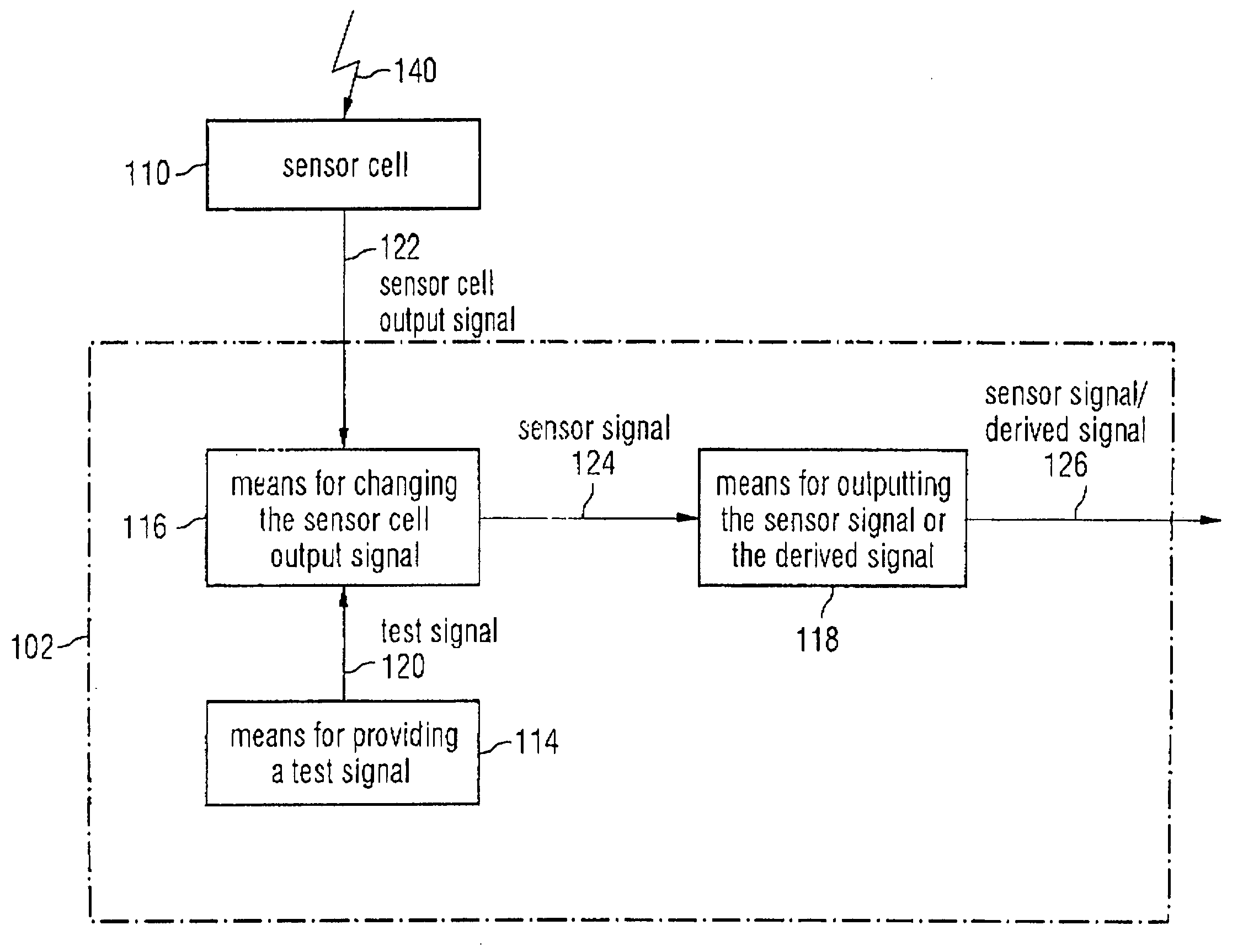
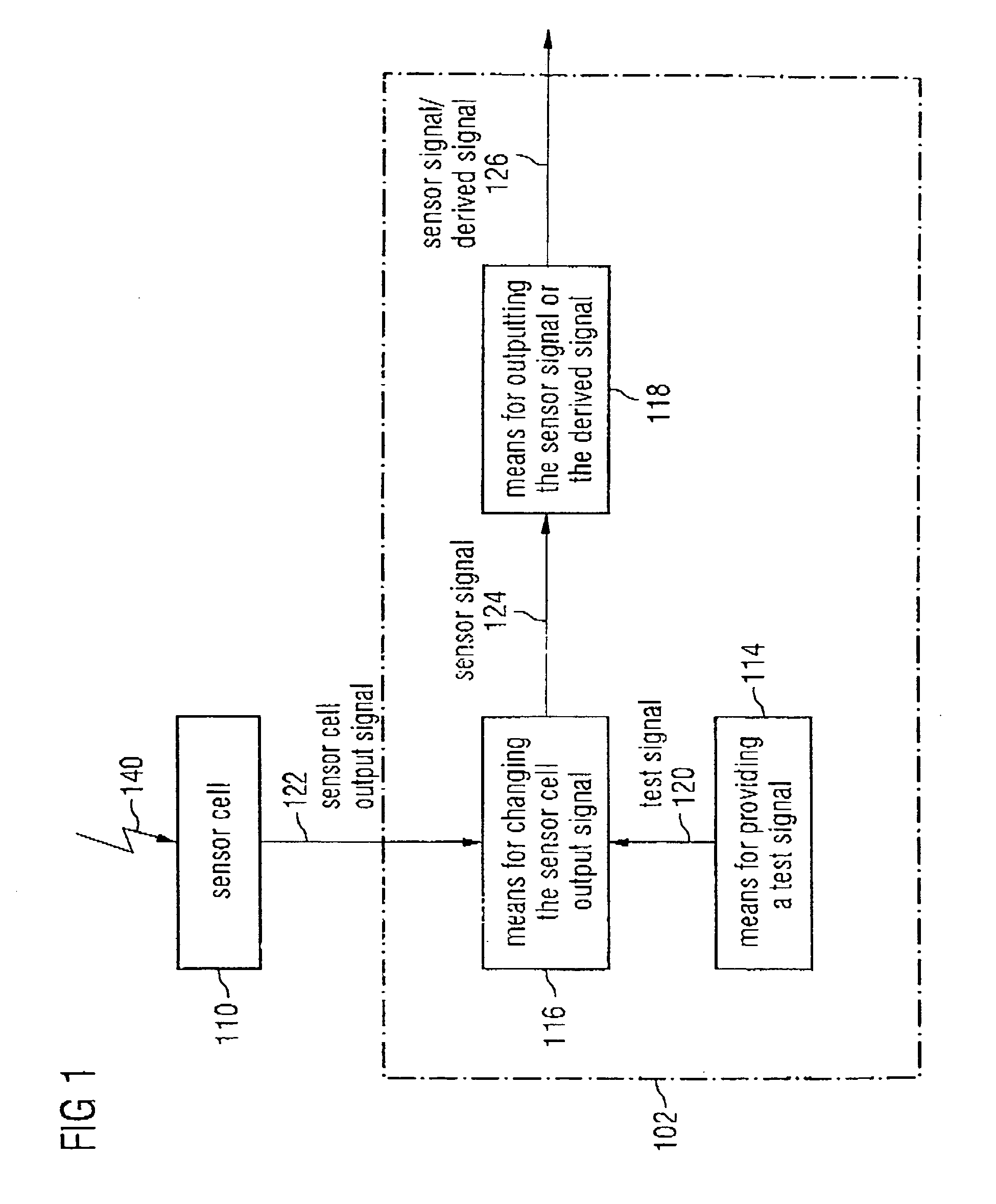
[0025] In FIG. 1 a sensor means is shown, comprising a device 102 for generating a sensor signal for an in-operation test of a signal path from a sensor cell 110 to an evaluation location (shown in FIG. 2). The device 102 for generating a sensor signal comprises means 114 for providing a test signal, means 116 for changing the sensor cell output signal and means 118 for outputting the sensor signal or the derived signal. Means 114 for providing a test signal is implemented for providing a test signal 120. Means 116 for changing the sensor cell output signal is coupled to means 114 via the test signal 120 for providing a test signal and to the sensor cell via a sensor cell output signal 122 provided by the sensor cell 110. Means 116 for changing the sensor cell output signal is implemented in order to provide a sensor signal 124 according to a predetermined change regulation in response to the sensor cell output signal 122 and the test signal 120. The sensor signal 124 contains both ...


PUM


Abstract

A device for generating a sensor signal suitable for an in-operation test of a signal path from a sensor cell to an evaluation location. The sensor cell provides a sensor cell output signal depending on a physical magnitude to be detected which is changed in means for changing the sensor cell output signal according to a predetermined change regulation based on a test signal in order to obtain the sensor signal. A signal derived from the sensor signal is detected by a device for an in-operation test of the signal path and is evaluated.

Description

PRIORITY [0001] This application claims priority to German application no. 103 37 045.5 filed Aug. 12, 2003. TECHNICAL FIELD OF THE INVENTION [0002] The invention relates to an in-operation test of a signal path, and in particular to the in-operation test of a signal path between a sensor cell and an evaluation location. DESCRIPTION OF THE RELATED ART [0003] Sensors use the change of electronic parameters of a device (sensor cell) by an external influence (measured quantity). For example, in a capacitive pressure sensor the capacity of a capacitor changes when its membrane bends as a consequence of an increasing pressure. A measurement circuit consequently measures the change of the electric parameters of a sensor cell and converts the same into an output voltage or a digital. The output voltage or the digital value is subsequently transmitted via a signal path to an evaluation circuit and evaluated by the same. [0004] Sensor devices, like pressure or temperature sensors having an a...

Claims


Application Information

Patent Timeline
IPC IPC(8): G01D3/08G01D18/00G01D21/00G01L27/00G01R31/00G01R31/28G06F19/00
CPCG01R31/2829G01D3/08
Inventor HAMMERSCHMIDT, DIRK
Owner INFINEON TECH AG
Why Eureka
Try Eureka