

Transmission and compressor system
- Summary
- Abstract
- Description
- Claims
- Application Information
AI Technical Summary
Benefits of technology
Problems solved by technology
Method used
Image

Examples
Embodiment Construction
[0014]Hereinafter, embodiments of a transmission and a compressor system according to the present disclosure will be described with reference to the accompanying drawings. However, the present disclosure is not limited to the embodiments only.
[0015](Configuration of Compressor System)
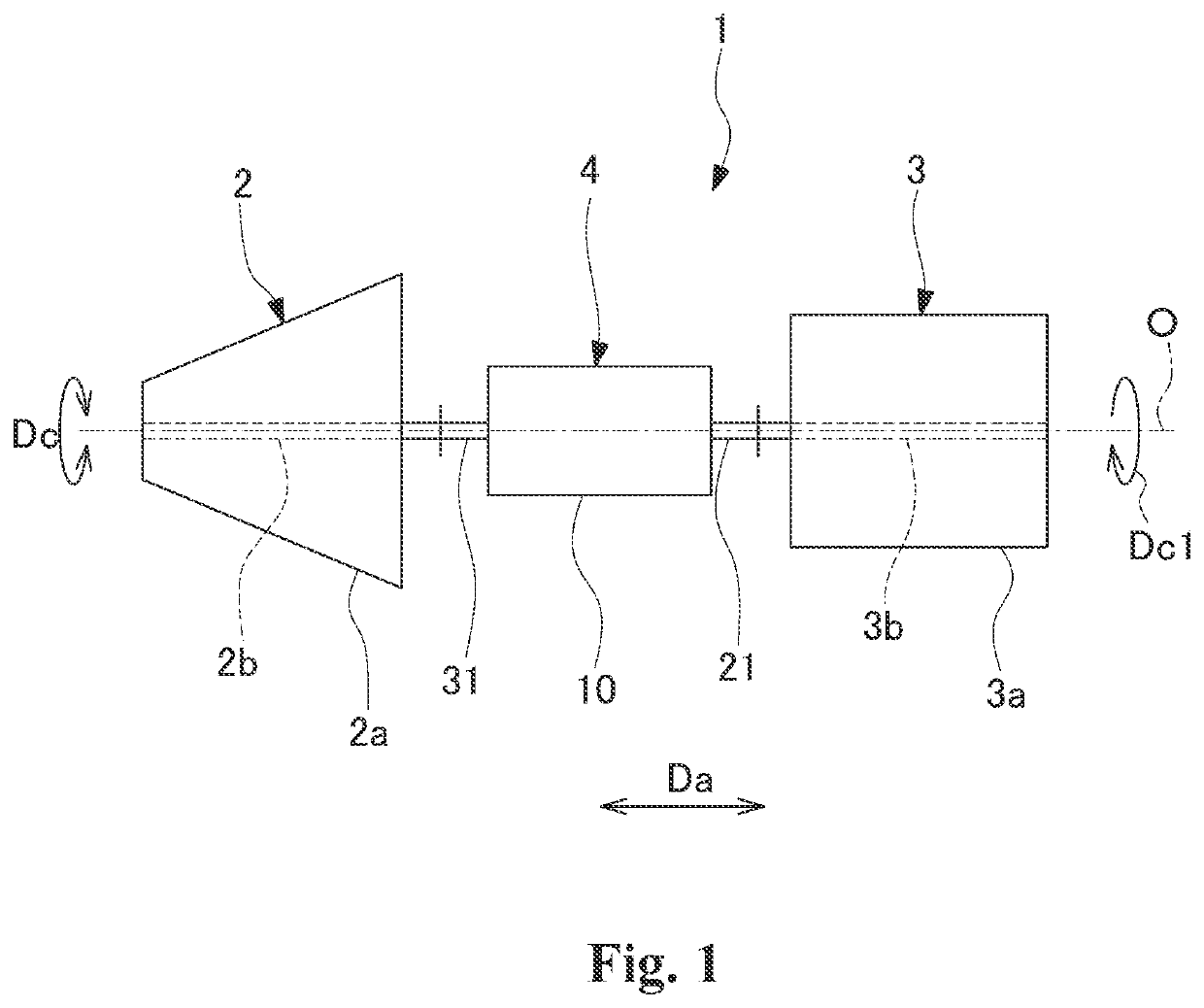
[0016]Hereinafter, a transmission and a compressor system according to an embodiment of the present disclosure will be described with reference to FIGS. 1 to 4. As illustrated in FIG. 1, a compressor system 1 includes a compressor 2, a driving machine 3, and a transmission 4.
[0017](Configuration of Compressor)
[0018]The compressor 2 includes a compressor housing 2a and a rotor 2b. The compressor housing 2a accommodates the rotor 2b extending about an axis O. The rotor 2b extends in an axial direction Da in which the axis O extends. The rotor 2b is rotatably supported by the compressor housing 2a in a circumferential direction Dc around the axis O. A rotation of a motor rotor 3b of the driving machine 3 i...
PUM
 Abstract
Description
Claims
Application Information