Percussion transducer

a transducer and percussion technology, applied in the field of electronic percussion instruments, can solve the problems of unbalanced striking surfaces, unintentional rotation of striking surfaces, and unbalanced striking surfaces that require additional mechanisms

Inactive Publication Date: 2005-02-24
WACHTER MARTIN RICHARD
View PDF11 Cites 38 Cited by
  • Summary
  • Abstract
  • Description
  • Claims
  • Application Information

AI Technical Summary

Benefits of technology

[0018] In accordance with another feature of the invention, a relatively thin protective covering layer of a resilient material may be provided over the outer surfaces of a piezo electric percussion transducer assembly so as to dampen high-frequency resonances, function as a reinforcement and provide protection from normal wear and tear.
[0021] Central mounting allows the striking surface to remain balanced.
[0023] Central mounting allows an even radial response and positional sensing from the center of the striking surface.
[0024] Central mounting does not require attachment to the striking surface, and therefore allows the user to remove or interchanging the striking surface without disconnecting the electronics. For example, in the case of a cymbal, the ring shaped transducer may be mounted on the cymbal stand and attached to the electronics, and coupled to the striking surface by releasably bolting the striking surface to the ring shaped transducer.
[0027] Central mounting allows the striking surface to exhibit natural playing characteristics such as free rotation, proper swing, and natural stick response.
[0035] To provide a percussion trigger that allows the striking surface to remain balanced.

Problems solved by technology

There are several disadvantages to this approach.
Problems associated with current percussion transducers include: The use of a flat disc shaped transducer prohibits central mounting on the same axis as the striking surface.
Flat transducers attached directly to the striking surface at locations other than the center cause the striking surface to become unbalanced.
Unbalanced striking surfaces require additional mechanisms to prevent the striking surface from unintentionally rotating and tipping over.
It is difficult to use conventional cymbals for striking surfaces as the piezo transducers can't be reliably attached to the striking surface and the conventional cymbal's motion and playability are compromised.
Poor positional sensing because the piezo transducer is not centrally located.
As the striking surface swings after impact, the electrical connection to the piezo transducer, its connections, or the striking surface may be broken due to the changing distances caused by the swinging motion.

Method used


Image

  • Percussion transducer
  • Percussion transducer
  • Percussion transducer

Examples


Embodiment Construction

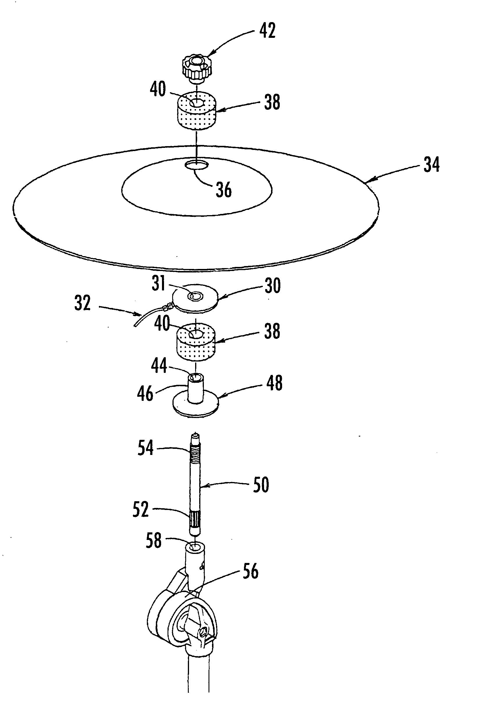
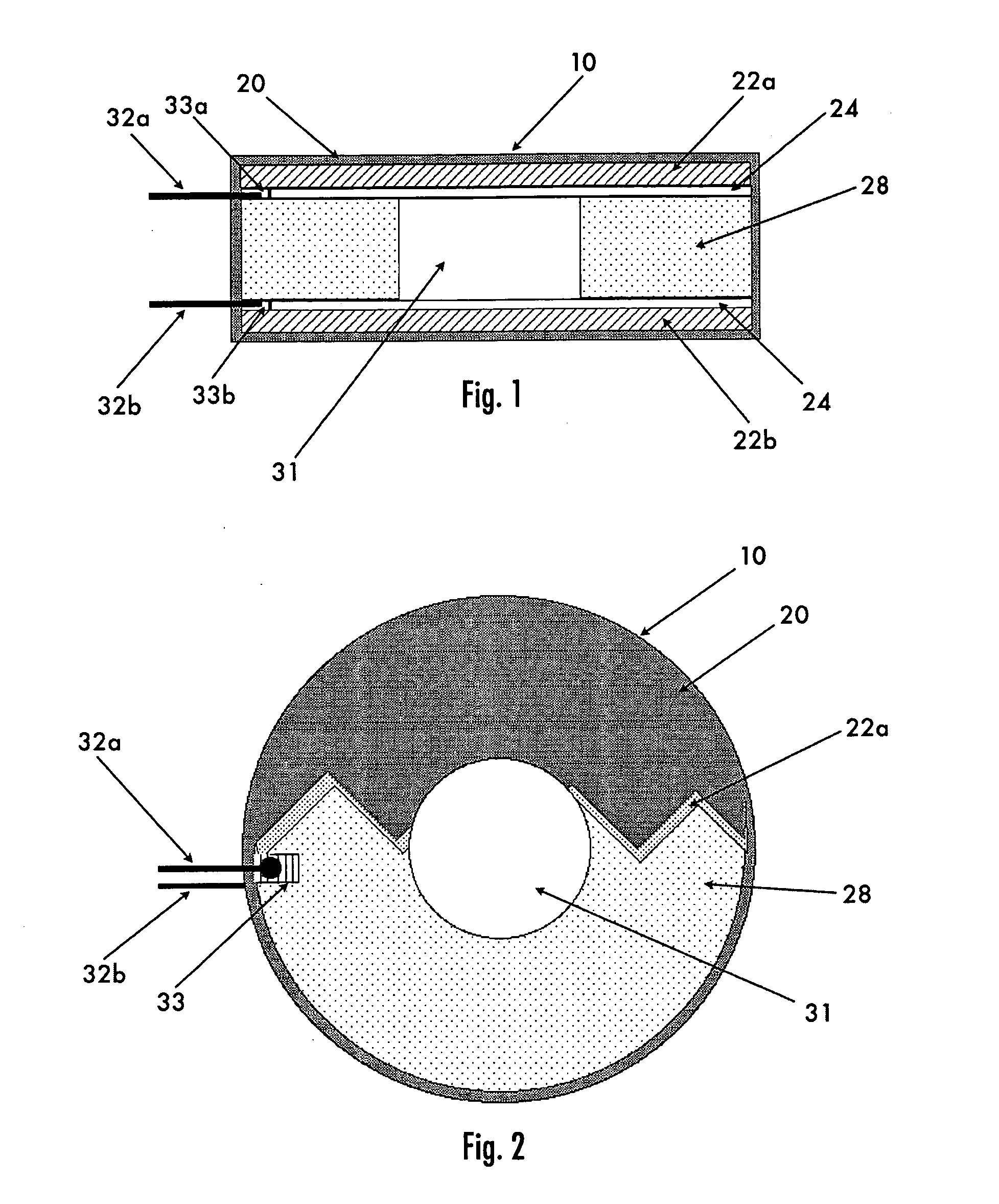
[0045] Referring to the drawings, the invention is a novel device for transferring mechanical vibrations of percussion instruments (i.e., instruments having a striking surface) into electrical trigger pulses utilizing a ring shaped percussion transducer suitable for being centrally mounted in relation to the striking surface of the percussion instrument. The ring shaped percussion transducer is illustrated in FIG. 1.

[0046] Using a ring shaped piezo ceramic transducer, instead of a flat piezo disc such as described in U.S. Pat. No. 4,984,498, allows the transducer to be centrally mounted in relation to the striking surface of the percussion instrument and share the radial center. The ring transducer is mounted on the same axis as the striking surface. Although the ring transducer could be mounted anywhere along the spindle mount, it is most effective when acoustically coupled to the striking surface. This provides maximum sensitivity while reducing sympathetic vibrations from other ...


PUM


Abstract

A ring-shaped percussion transducer for converting a striking impact into a representative electrical pulse triggering signal is suitable for mounting on the center axis of a percussion instrument. In a preferred embodiment, the transducer is formed of a piezo electric material of ring shape; protected on the top and bottom by thinner ring shaped washers; enclosed in a protective coating and mounted along the center axis of a percussion device which when struck transmits vibrations to the percussion transducer. The percussion transducer is connected to conventional downstream electronics so as to produce a sound responsive to the striking impact.

Description

[0001] This application is entitled to, and claims the benefit of, priority from U.S. Provisional Application Ser. No. 60 / 496,150, filed Aug. 19, 2003.FIELD AND BACKGROUND OF THE INVENTION [0002] 1. Field of the Invention [0003] The present invention relates in general to electronic percussion instruments, and more particularly to a novel transducer for use therein. [0004] 2. Background Information [0005] Electronic percussion instruments are a class of musical instruments which are designed to be played like traditional acoustic percussion instruments but offer an unlimited spectrum of sounds, ranging from the emulation of real acoustic instruments to heavily synthesized abstract sounds and noises. Electronic percussion instruments are comprised of a striking surface that the user strikes with their hand, foot or other implement such as a stick or mallet, a means to sense the strike and transfer it from acoustic energy into an electrical pulse (a transducer), and downstream electro...

Claims


Application Information

Patent Timeline
Patent Type & Authority Applications(United States)
IPC IPC(8): G10H3/14
CPCG10H3/146G10H2230/321G10H2220/551
Inventor WACHTER, MARTIN RICHARD
Owner WACHTER MARTIN RICHARD
Why Eureka
Try Eureka