Multi-sensor guidance system for extreme force launch shock applications

a multi-sensor guidance and shock technology, applied in the direction of navigation instruments, process and machine control, instruments, etc., can solve the problems of extremely expensive process, component failure, and imu system impedance sensors being susceptible to failur

Inactive Publication Date: 2005-02-24
HUA CUONG TU
View PDF21 Cites 43 Cited by
  • Summary
  • Abstract
  • Description
  • Claims
  • Application Information

AI Technical Summary

Benefits of technology

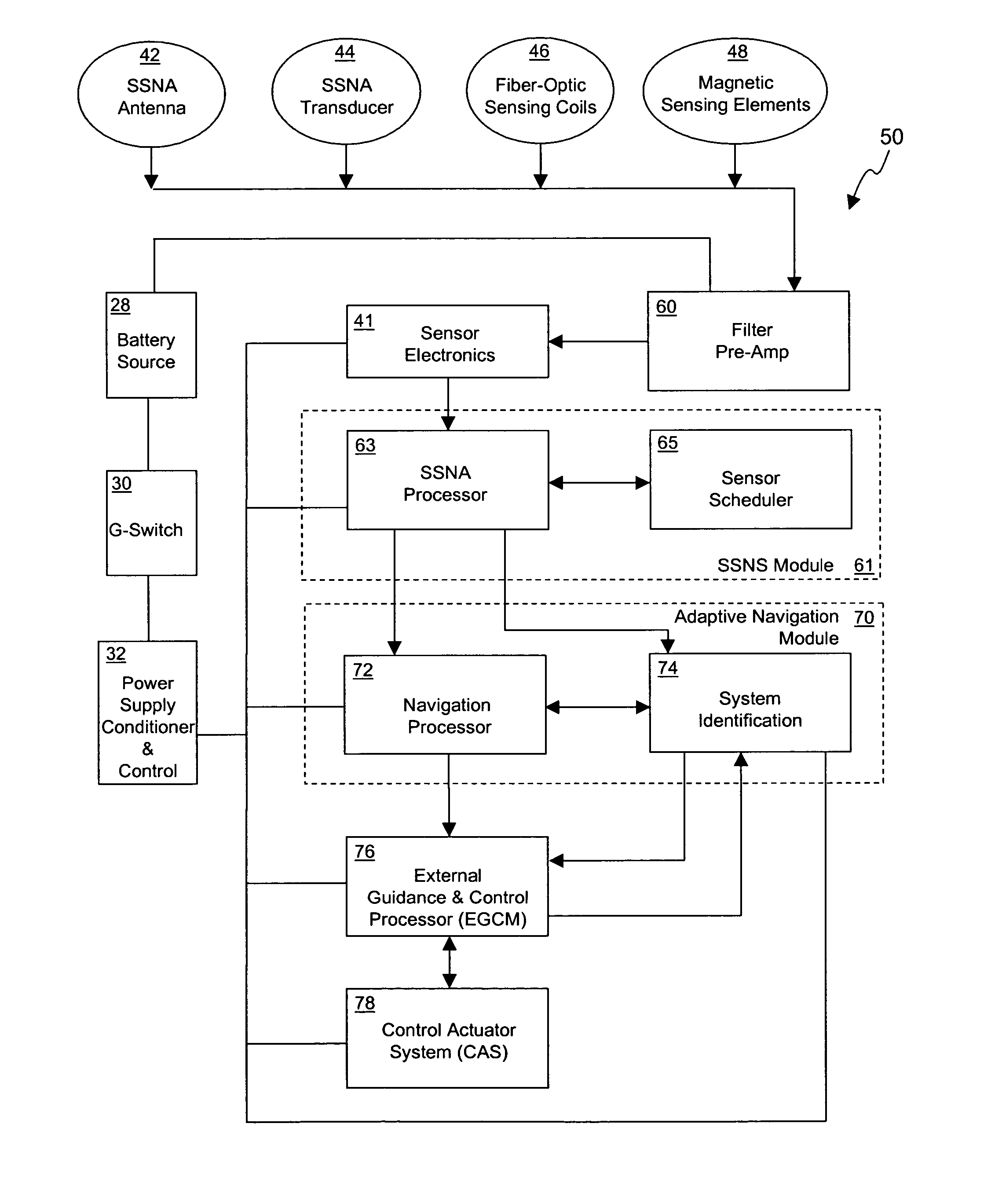
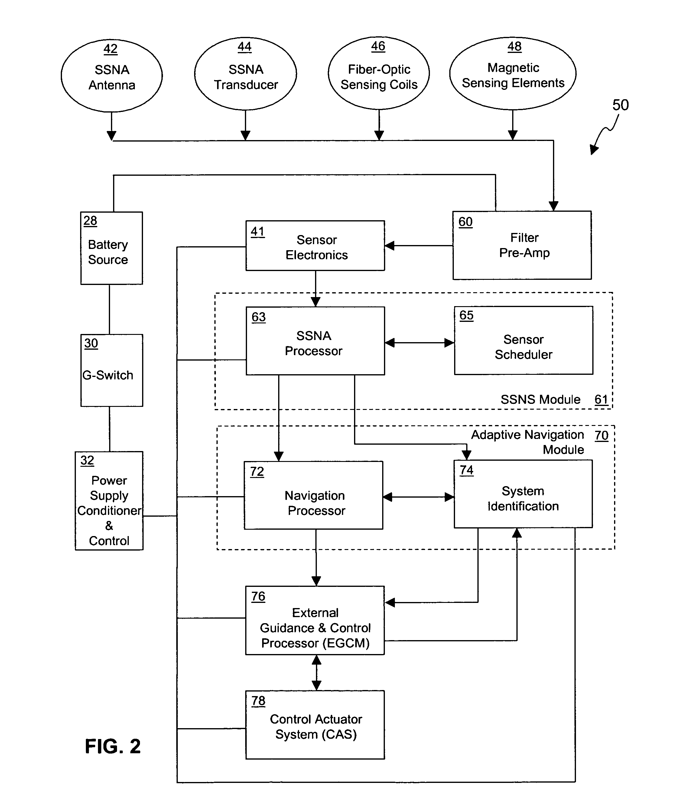
[0006] A projectile navigation system operable within an extremely high G-shock loading environment during the launch phase may include a set of Kalman filter equations configured to repeatedly calculate a navigational solution by solving a set of non-linear equations of motions of the projectile utilizing a current parameter vector, position, velocity, and attitude of the projectile. The system may include a suite of solid state sensors to calibrate the Kalman filter equations. If desired, the system may also include a satellite based positioning-determining (SBPD) attitude determination system configured to update the state of the host projectile by making real time attitude measurements of the projectile, and a parameter estimator configured to estimate and update a parameter vector of the host projectile. An external guidance and control processor may be used to generate guidance and control signals, enabling real time navigation of the host projectile.

Problems solved by technology

Not surprisingly, the inertial sensors of the IMU system (swinging proof masses and spinning gyroscopes) are susceptible to failure.
To improve the reliability of these systems, the design of IMU system components undergo a process known as G-hardening, which is an extremely expensive process.
However, even after the IMU components have undergone a G-hardening process, these components are susceptible to failure when subjected to extreme G-forces.
While there have been attempts to design durable and reliable guidance systems that may be configured with thrusted and non-thrusted flight vehicles, these attempts have not been entirely successful

Method used


Image

  • Multi-sensor guidance system for extreme force launch shock applications
  • Multi-sensor guidance system for extreme force launch shock applications
  • Multi-sensor guidance system for extreme force launch shock applications

Examples


Embodiment Construction

[0020] In the following description of the preferred embodiments, reference is made to the accompanying drawing, which form a part hereof, and which show by way of illustration, specific embodiments of the invention. It is to be understood by those of ordinary skill in this technological field that other embodiments may be utilized, and structural, electrical, as well as procedural changes may be made without departing from the scope of the present invention.

[0021] First of all, in many embodiments, the present invention may be implemented as a NG&C system for thrusted and non-thrusted flight vehicles and projectiles. As will be described herein, the ballistic trajectory of a projectile is very well defined, and the body motion of the projectile itself may be used as an inertial sensor implemented in software using, for instance, an adaptive Kalman filter. As will be described in detain herein, many embodiments of the present invention provide a NG&C system that is operable without...


PUM


Abstract

A projectile navigation system operable within an extremely high G-shock loading environment during the launch phase may include a set of Kalman filters configured to repeatedly calculate a navigational solution by solving a set of non-linear equations of motions of the projectile utilizing a current parameter vector, position, velocity, and attitude of the projectile. The system may include a suite of solid state sensors to calibrate the Kalman filter equations. If desired, the system may also include a satellite based positioning-determining (SBPD) attitude determination system configured to update the state of the host projectile by making real time attitude measurements of the projectile, and a parameter estimator configured to estimate and update a parameter vector of the host projectile. An external guidance and control processor may be used to generate guidance and control signals, enabling real time navigation of the host projectile.

Description

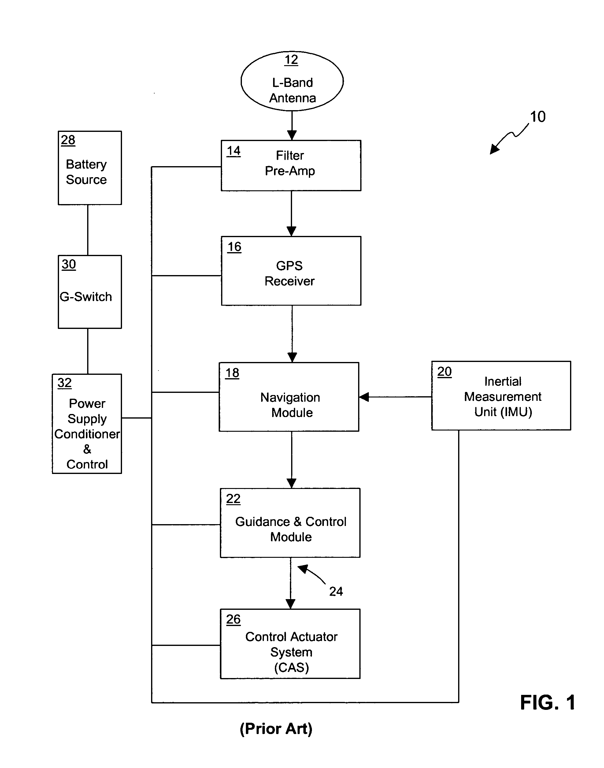
BACKGROUND OF THE INVENTION [0001] 1. Field of the Invention [0002] The present invention relates generally to a guidance system, and in particular to a solid state guidance system configurable with a host projectile and operable within an extreme force launch shock environment. [0003] 2. Description of the Related Art [0004] Currently available navigation, guidance, and control (NG&C) systems for projectiles, missiles, and space vehicles, that operate in benign flight environments, typically include GPS-based guidance systems combined with an inertial navigation system (INS). Typical INS systems include an inertial measurement unit (IMU) designed to measure motions of a host vehicle. In many systems, the IMU unit measures the swing of the proof masses of its accelerometers to infer translational accelerations of the host vehicle. Similarly, the IMU unit measures the movement of its spinning gyroscopes about their respective axes to calculate rotational rates. [0005] The accuracy of...

Claims


Application Information

Patent Timeline
Patent Type & Authority Applications(United States)
IPC IPC(8): G05D1/03G05D1/12
CPCF42B15/01G05D1/12G01S19/54G01S19/48G05D1/107G01S19/45
Inventor HUA, CUONG TU
Owner HUA CUONG TU
Why Eureka
Try Eureka