Spark plug

Inactive Publication Date: 2005-02-24
LINDSAY FAMILY REVOCABLE TRUST
View PDF26 Cites 5 Cited by
  • Summary
  • Abstract
  • Description
  • Claims
  • Application Information

AI Technical Summary

Benefits of technology

[0009] The present invention resides in a spark plug which produces greater horsepower than prior spark plugs while decreasing fuel consumption. The spark plug also prevents fouling, or the build-up of carbon and oil deposits on

Problems solved by technology

This is referred to as spark plug fouling which causes incomplete burning of the air/fuel mixture, possibly to a point of non-ignition.
The core nose may begin to glow above 850 ° C., potentially causing the spark plug core nose to self-destruct by explosion.
Aside from the loss of the spark plug, other internal components of the engine can also be severely damaged by a glowing spark plug.
Any accumulations of oil or carbon not located directly in the path of spark firing, such as those deposits on the insulator surface, will remain adhered and ad

Method used


Image

  • Spark plug
  • Spark plug
  • Spark plug

Examples


Embodiment Construction

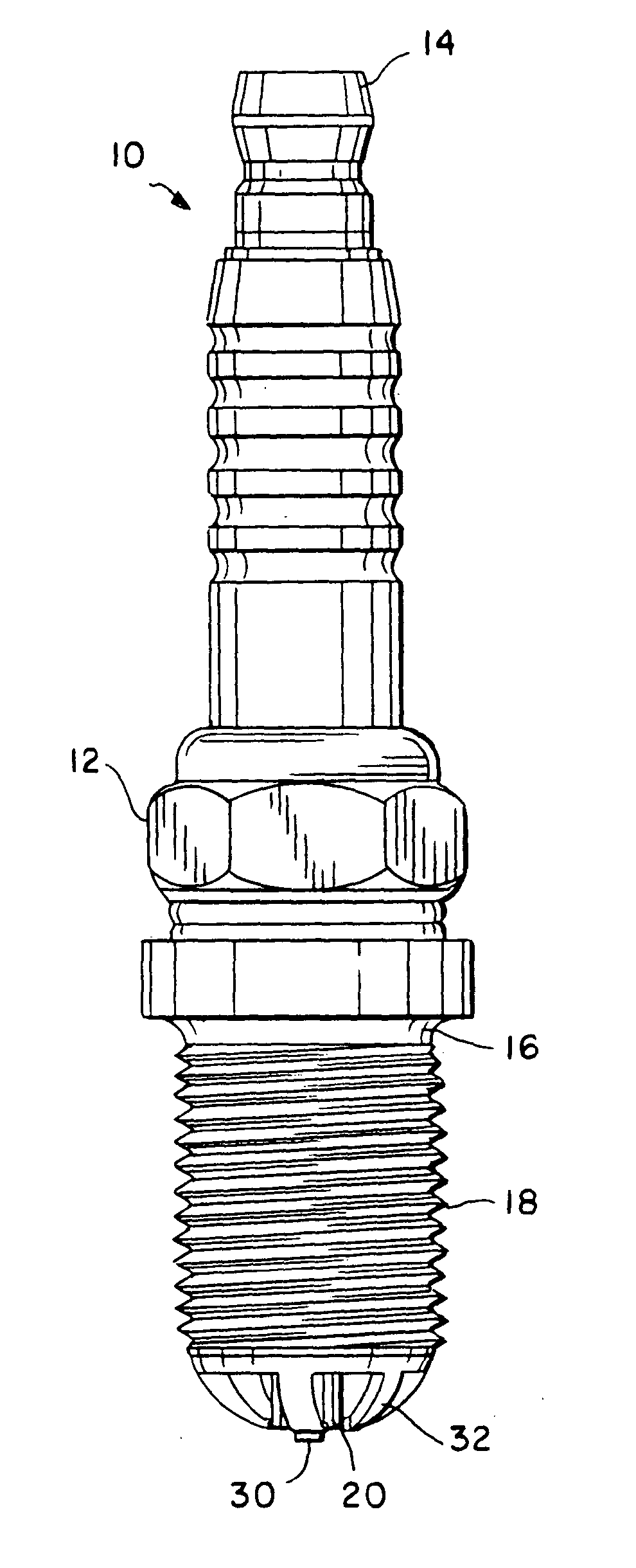
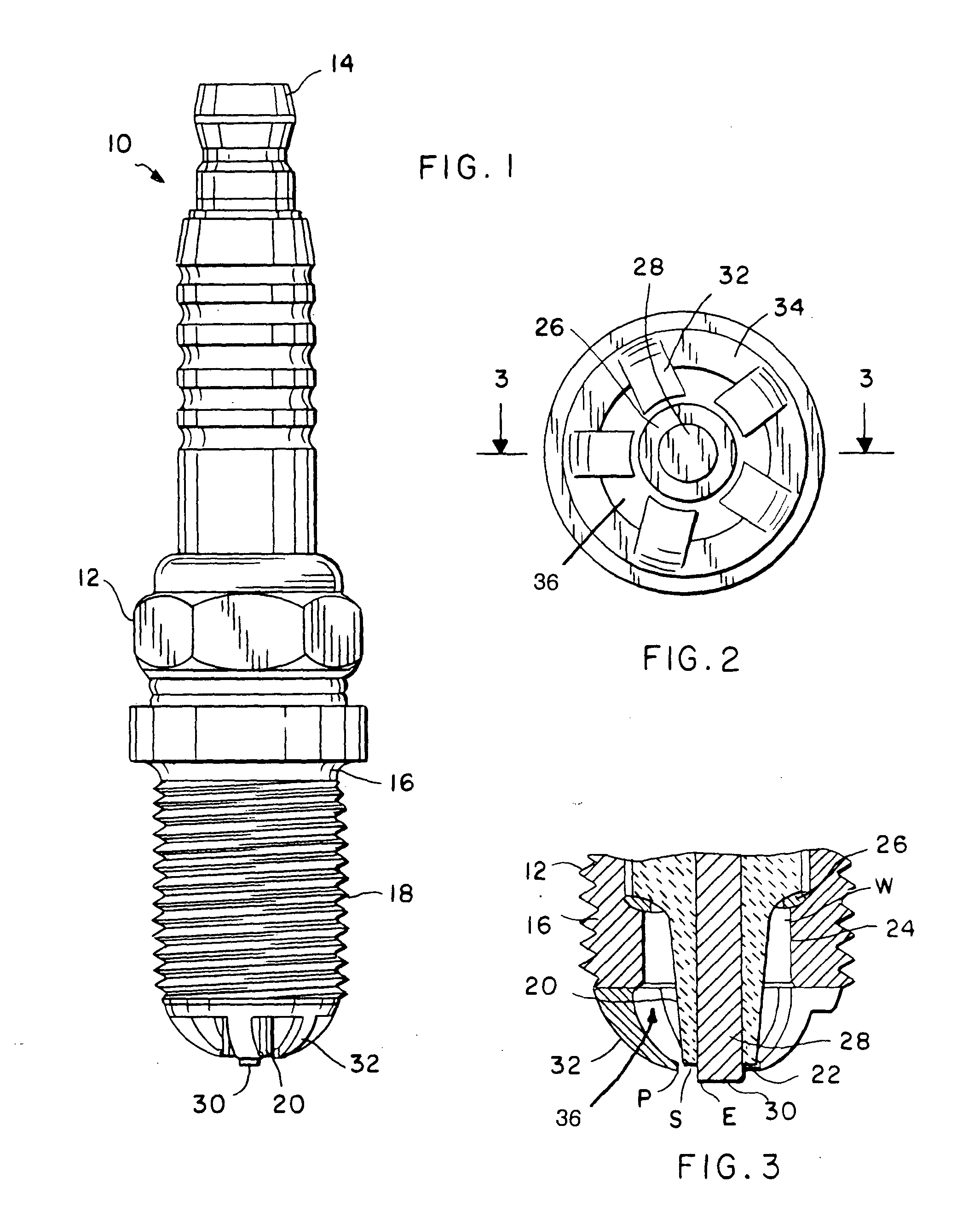
[0024] As shown in the drawings for purposes of illustration, the present invention is concerned with a spark plug, generally referred to in the drawings by the reference number 10. As illustrated in FIGS. 1-3, the spark plug 10 has an outer elongated tubular housing 12 having an upper end which is formed into a terminal 14. This terminal 12 is electrically connected to the ignition system of the engine which supplies the electrical energy to power or fire the spark plug 10. At the opposite end of the spark plug 10 is formed a base 16. A portion of the exterior surface of the housing 12, typically adjacent the base 16, includes a series of screw threads 18. The purpose of the screw threads 18 is to facilitate mounting the spark plug 10 within a receiving hole of an engine which accesses a combustion chamber.

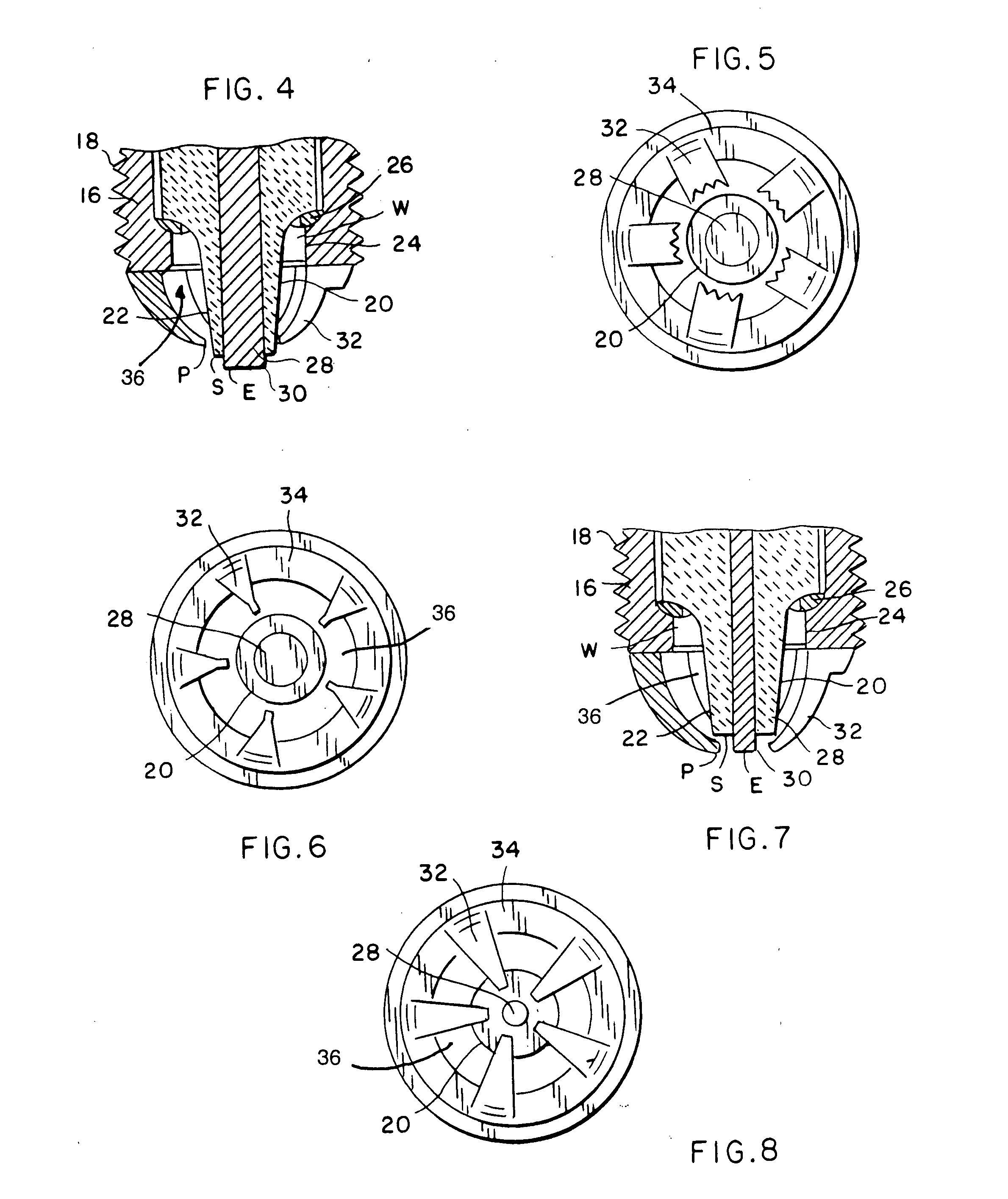
[0025] Mounted within the tubular housing 12 is an insulator 20. The insulator 20 typically comprises a non-conductive and heat resistant material. The insulator 20 extends from...


PUM


Abstract

A spark plug includes an elongated tubular housing with a central longitudinal axis and a terminal at one end and a base having an inner side wall opposite the terminal. A portion of the internal side wall is platinum-plated. An inner chamber is formed within the housing in which is mounted an insulator. At least a portion of the insulator extends from the base and tapers to a core nose. An electrode is embedded within the insulator, a tip of which protrudes from the insulator. Ground prongs extend from the base towards the central longitudinal axis of the housing to an end. The ground prongs may have sharp edges for increased spark presentation. A ground ring may be connected to the base, from which the ground prongs extend. Electrical resistance of the spark plug is selected so that the generated spark will travel from the center electrode to the surface of the insulator and through an air gap to an end of a ground prong.

Description

BACKGROUND OF THE INVENTION [0001] The present invention relates to spark plugs. More particularly, the present invention relates to a spark plug for an internal combustion engine which utilizes a surface and air gap spark path for anti-fouling and improved performance in operating efficiency while requiring less energy for spark generation. [0002] Spark plugs are used in most internal combustion engines to provide high voltage sparks which ignite an air and fuel mixture within combustion chambers of an engine. During operation, a spark generating system delivers a pulse of electrical energy in the form of a high voltage to the terminal of the spark plug at timed intervals which are intended to coincide with combustion chamber piston placement. The spark plug directs the high voltage energy to jump or spark between a center electrode and a ground electrode of the spark plug. As the spark travels across the air gap of the center and ground electrodes, the compressed air / fuel mixture ...

Claims


Application Information

Patent Timeline
IPC IPC(8): H01T13/46
CPCH01T13/467
Inventor LINDSAY, MAURICE E.
Owner LINDSAY FAMILY REVOCABLE TRUST
Why Eureka
Try Eureka