Concentric internal combustion rotary engine

a rotary engine and internal combustion technology, applied in the field of combustion engines, can solve the problems of inefficient way in which components are repeatedly accelerated, stopped, reversed during engine operation, and conventional piston-based engines are both unbalanced and inefficient, and about 13% of fuel energy is lost in a conventional piston-based engine. , to achieve the effect of high horsepower, low emissions and high torqu

Active Publication Date: 2007-03-29
CLR
View PDF18 Cites 7 Cited by
  • Summary
  • Abstract
  • Description
  • Claims
  • Application Information

AI Technical Summary

Benefits of technology

[0014] It is an object of the invention to provide an internal combustion rotary engine that has high horsepower, very high torque, and very low emissions. It is a further object of the invention to provide an internal combustion rotary engine that is balanced and uses a rotor that rotates about a single axis. It is yet another object of the invention to provide an internal combustion rotary engine that uses a concentrically balanced rotor.

Problems solved by technology

First and foremost is the inefficient manner in which components such as, for example, pistons are repeatedly accelerated, stopped, and reversed during operation of the engine.
In this regard, conventional piston-based engines are both unbalanced and inefficient due to the constant momentum changes occurring within the engine.
It has been estimated, for example, that about 13% of fuel energy is lost in a conventional piston-based engine due to internal friction and pumping losses.
In fact, a true 90° (optimal) torque arm is never achieved in a conventional piston-based combustion engine.
First, internal combustion rotary engines are more lightweight and compact.
Fifth, internal combustion rotary engines have a generally flat torque curve because no valves are used.
The problem with Wankel-type internal combustion rotary engines is that they generally leak combustion gases, making these types of engines less desirable.
In addition, the rotational speed (i.e., revolutions per minute (RPM)) of Wankel-type internal combustion rotary engines is limited because of the manner in which the triangular rotor flip-flops around the interior of the epitrochoid housing.

Method used


Image

  • Concentric internal combustion rotary engine
  • Concentric internal combustion rotary engine
  • Concentric internal combustion rotary engine

Examples


Embodiment Construction

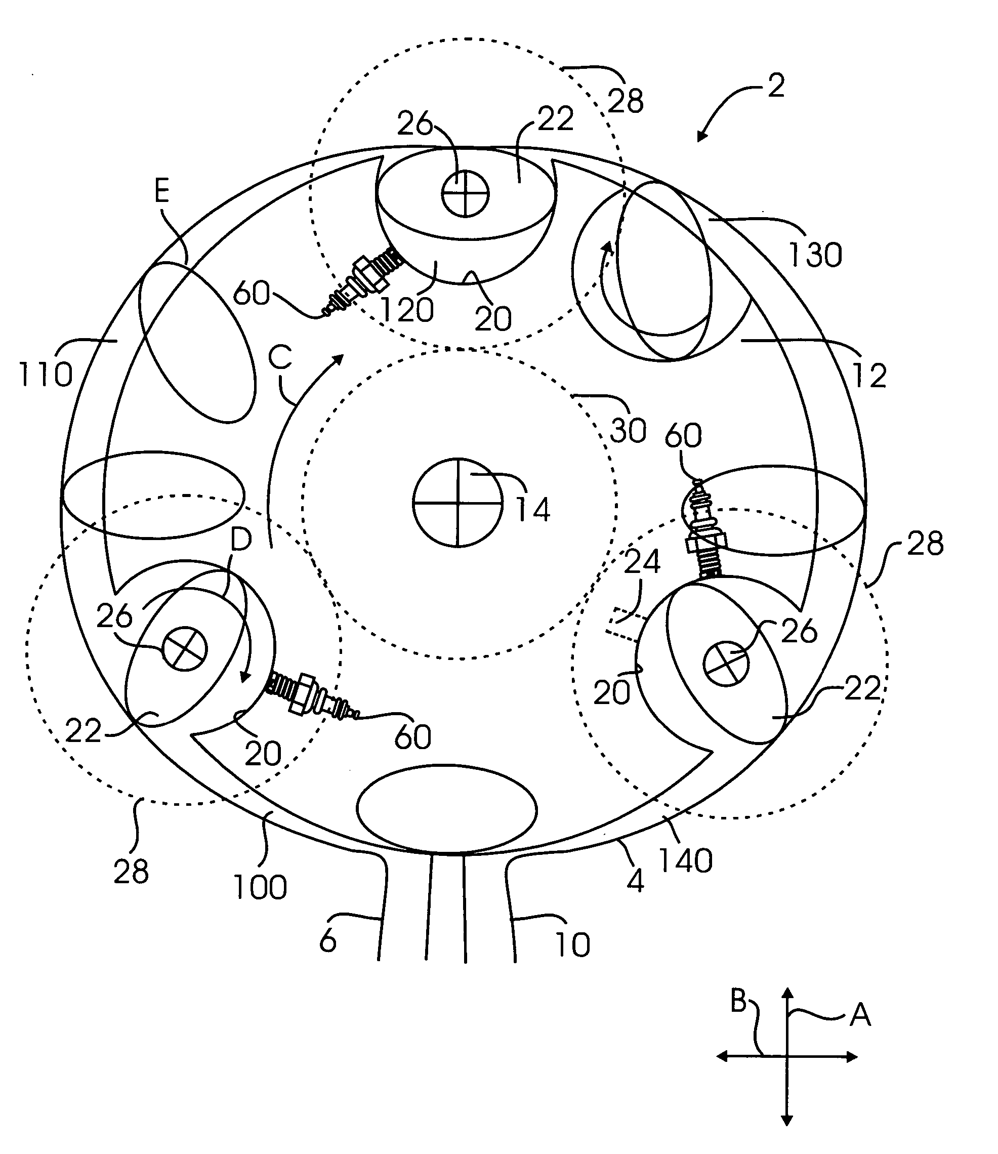
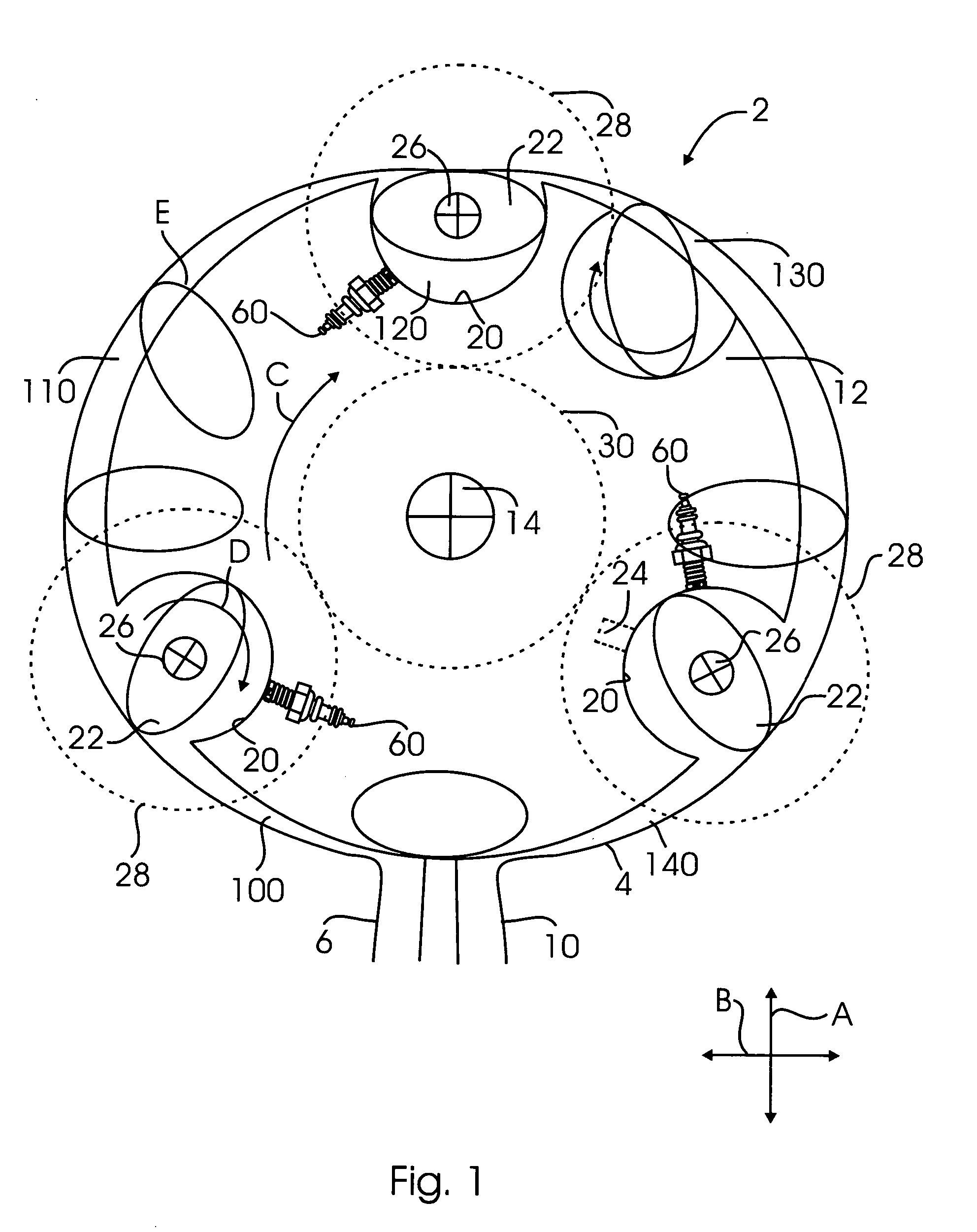
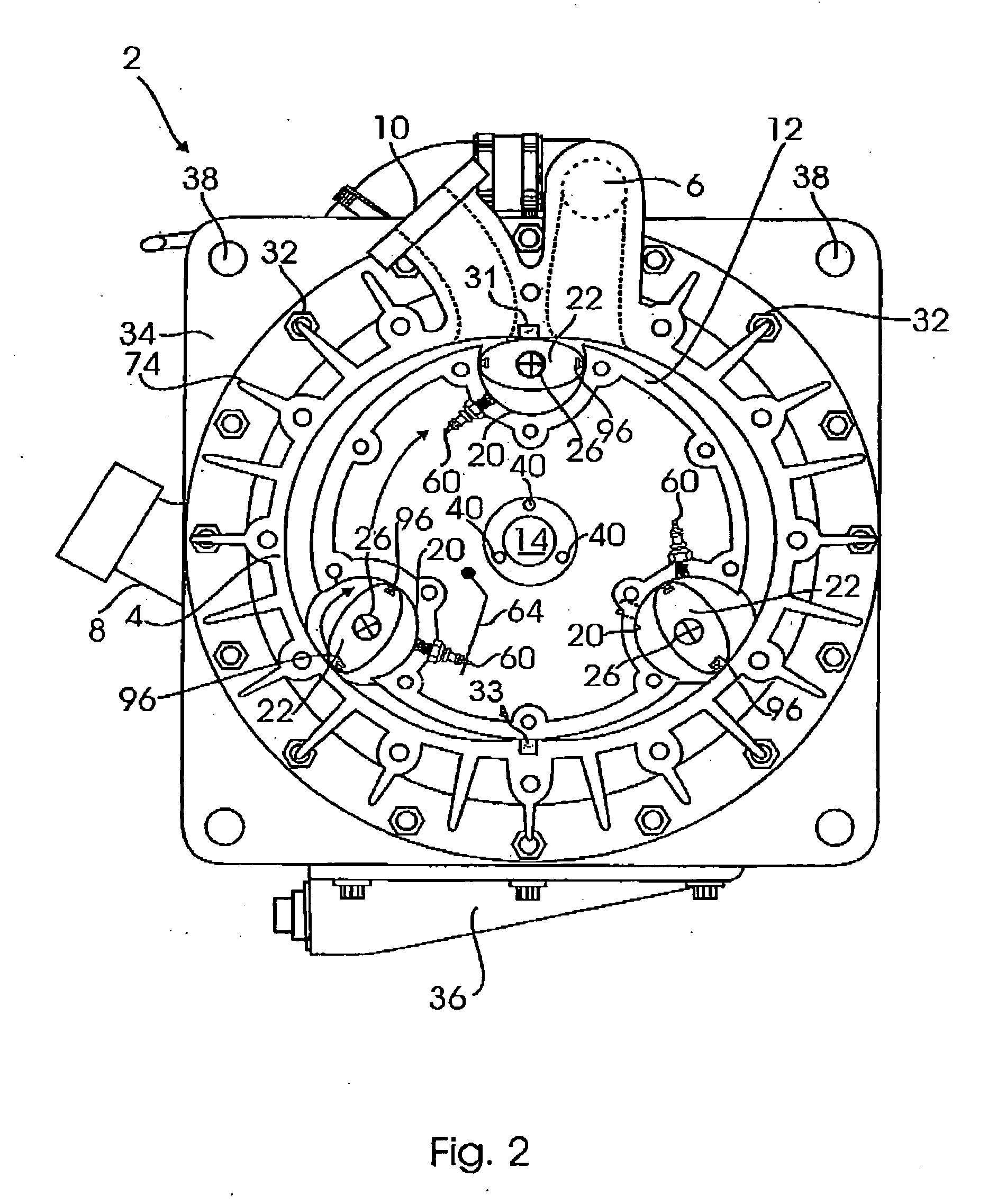
[0027]FIGS. 1 and 2 illustrates an internal combustion rotary engine 2 according to a preferred embodiment of the invention. The internal combustion rotary engine 2 includes a housing 4 which is generally oblong-shaped having a minor axis (the distance between the top and bottom portions of the housing 4 in the direction of arrow A shown in FIG. 1) and major axis (the distance between the left and right portions of the housing 4 in the direction of arrow B shown in FIG. 1). The housing 4 includes an inlet 6 which serves as the inlet for the fuel / air mixture which is combusted inside the engine 2. The inlet 6 may be coupled to an optional compressor 8, for example, as illustrated in FIGS. 7 and 8. The housing 4 further includes an outlet 10 which serves to exhaust combustion gases / air outside of the engine 2. In one aspect of the invention, the housing 4, when viewed in cross-section, has a profile of a spline curve.

[0028] A rotatable rotor 12 is disposed centrally inside the housin...


PUM


Abstract

An internal combustion rotary engine includes a housing having an inlet and an outlet and a rotatable rotor centrally mounted within the housing. The rotor includes a plurality of pockets located about its circumference, the rotor further being connected to a rotor shaft. A rotatable elliptical body is disposed in each of the plurality of pockets. Each rotatable elliptical body is coupled to respective planet gears and each respective planet gear is meshed with a centrally disposed fixed sun gear. An ignition source is disposed in each of the plurality of pockets for igniting a fuel / air mixture. During operation of the internal combustion rotary engine, for each 360° rotation of the rotor, each elliptical body rotates through 720°.

Description

REFERENCE TO RELATED APPLICATIONS [0001] This Application claims priority to U.S. Provisional Patent Application No. 60 / 587,948 filed on Jul. 14, 2004. The '948 Application is incorporated by reference as if set forth fully herein.FIELD OF THE INVENTION [0002] The field of the invention generally relates to combustion engines. More specifically, the field of the invention relates to internal combustion rotary engines. BACKGROUND OF THE INVENTION [0003] Combustion engines that operate using a reciprocating piston suffer from a number of disadvantages. First and foremost is the inefficient manner in which components such as, for example, pistons are repeatedly accelerated, stopped, and reversed during operation of the engine. In this regard, conventional piston-based engines are both unbalanced and inefficient due to the constant momentum changes occurring within the engine. It has been estimated, for example, that about 13% of fuel energy is lost in a conventional piston-based engine...

Claims


Application Information

Patent Timeline
Patent Type & Authority Applications(United States)
IPC IPC(8): F02B53/00
CPCF01C1/36F04C2250/301F03C2/306F01C11/008Y02T10/12F02B53/00F02B53/04F04C18/00
Inventor CAMPBELL, ROBERT L.
Owner CLR
Why Eureka
Try Eureka