Engine energy-saving and emission-reducing system coordinated by heat pipe and cold pipe and working method thereof

An energy-saving emission reduction, engine technology, applied in the engine energy-saving emission reduction system, "heat pipe" technology field, can solve the problems of low flash point, poor startability, and poor fluidity

Inactive Publication Date: 2010-02-10
段洪池 +3
View PDF0 Cites 7 Cited by
  • Summary
  • Abstract
  • Description
  • Claims
  • Application Information

AI Technical Summary

Problems solved by technology

[0002] Fossil fuels will be exhausted sooner or later. Therefore, a variety of renewable fuels have been developed in the energy field. Because the molecular composition of these new energy products is different from that of fossil energy, the technical indicators cannot be completely consistent with those of fossil energy, so there are some incompatibility. Problems, such as poor startability, poor fluidity, and low flash point, etc., can be solved by improving the engine; the thermal efficiency of the existing engine is only increased to about 30-40%, which is difficult to break through, and there is a lot of room for tapping the potential; mixing water Combustion technology, because the problem of oil-water stratification has not been solved, it cannot be promoted socially
Both swirl technology and air intake variable technology are existing technologies. Modern internal combustion engines often place swirlers at the end of the intake pipe, which reduces the intake resistance as much as possible and improves the fineness of the mixture; modern gasoline engines also use series and The "variable air intake" technology of disconnecting the 'curved slender tube' improves the air intake efficiency at low and medium speeds and maintains the highest air intake efficiency of the original machine, but it only saves 10% of fuel in practical use; It has been in the process of development, but it has not been successful. The main reason for the failure is that a little oil-water mixture remained in the device that supplied the oil-water mixture when it was stopped. During the storage time, the oil-water mixture separated by itself. Water enters the cylinder first, so it fails to ignite; the existing engine temperature adjustment method is mainly passive, and the sensor signal is sent to the microcomputer to adjust and solve it instead of preventing and controlling in advance; generally there are three main problems in bioenergy, starting Poor performance, poor fluidity and low flash point. The existing "switching use" technology can only be applied in spring, summer and autumn when the temperature is suitable. It only solves the problem of poor starting performance, but cannot solve the problems of poor fluidity and low flash point. It cannot be used around the clock; the exhaust gas treatment technology of existing engines is generally to use high-fine mesh purification parts to block the treatment, or to use re-burning means to purify the exhaust gas emitted, but there are three problems: ① the plugging type Comprehensive treatment increases the exhaust resistance, thus reducing the engine power and resulting in fuel consumption; ② Substances are indestructible, such as carbon and sulfur, no matter what kind of polyoxide is discharged in the form of transparent gas, carbon, sulfur, phosphorus, etc. It must always be discharged to pollute the atmosphere and cannot be eradicated; ③The high-temperature treatment method dissipates too much heat to the surrounding environment, which is an important factor for atmospheric warming

Method used


Image

  • Engine energy-saving and emission-reducing system coordinated by heat pipe and cold pipe and working method thereof
  • Engine energy-saving and emission-reducing system coordinated by heat pipe and cold pipe and working method thereof
  • Engine energy-saving and emission-reducing system coordinated by heat pipe and cold pipe and working method thereof

Examples


Embodiment 1

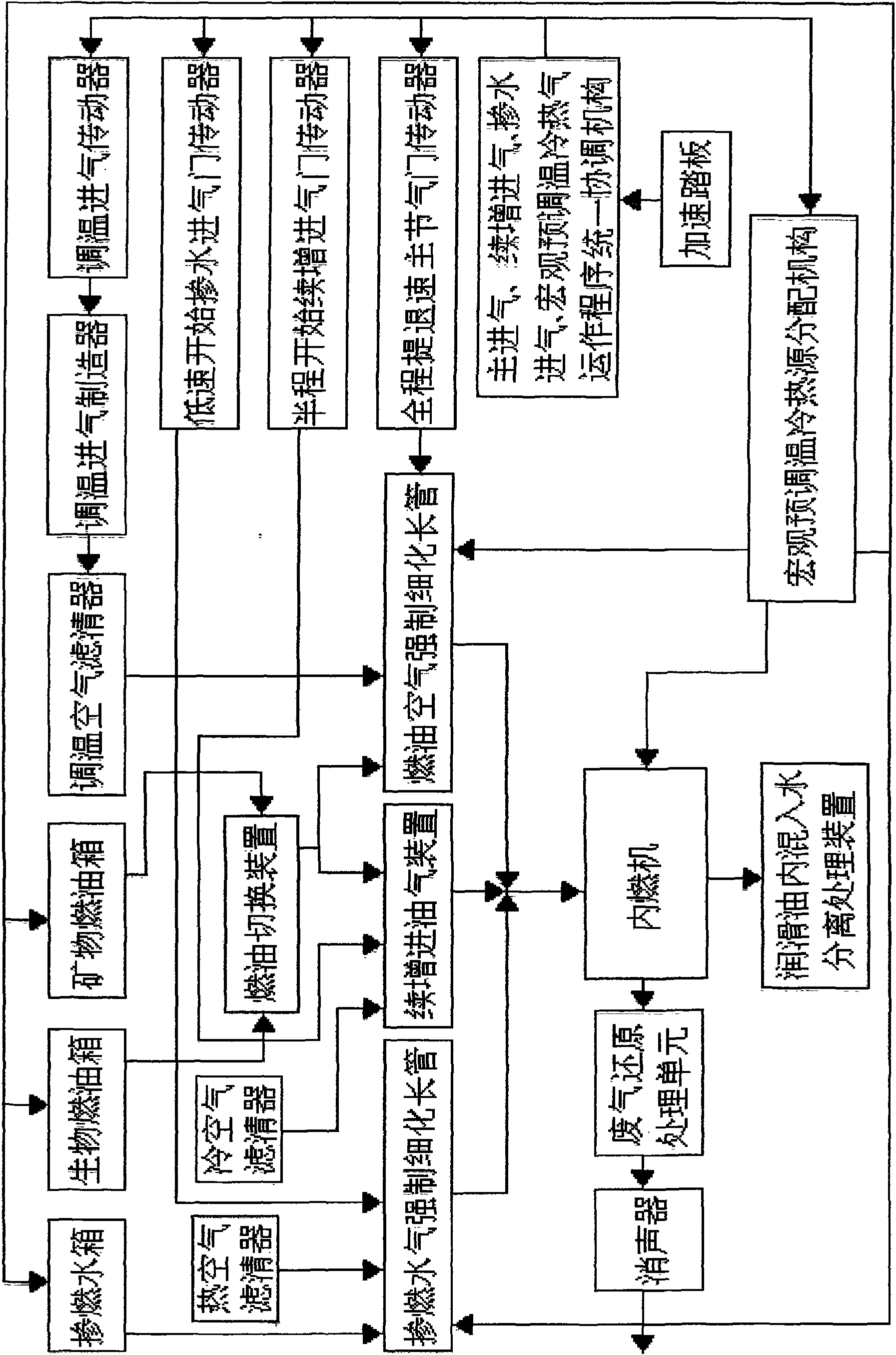
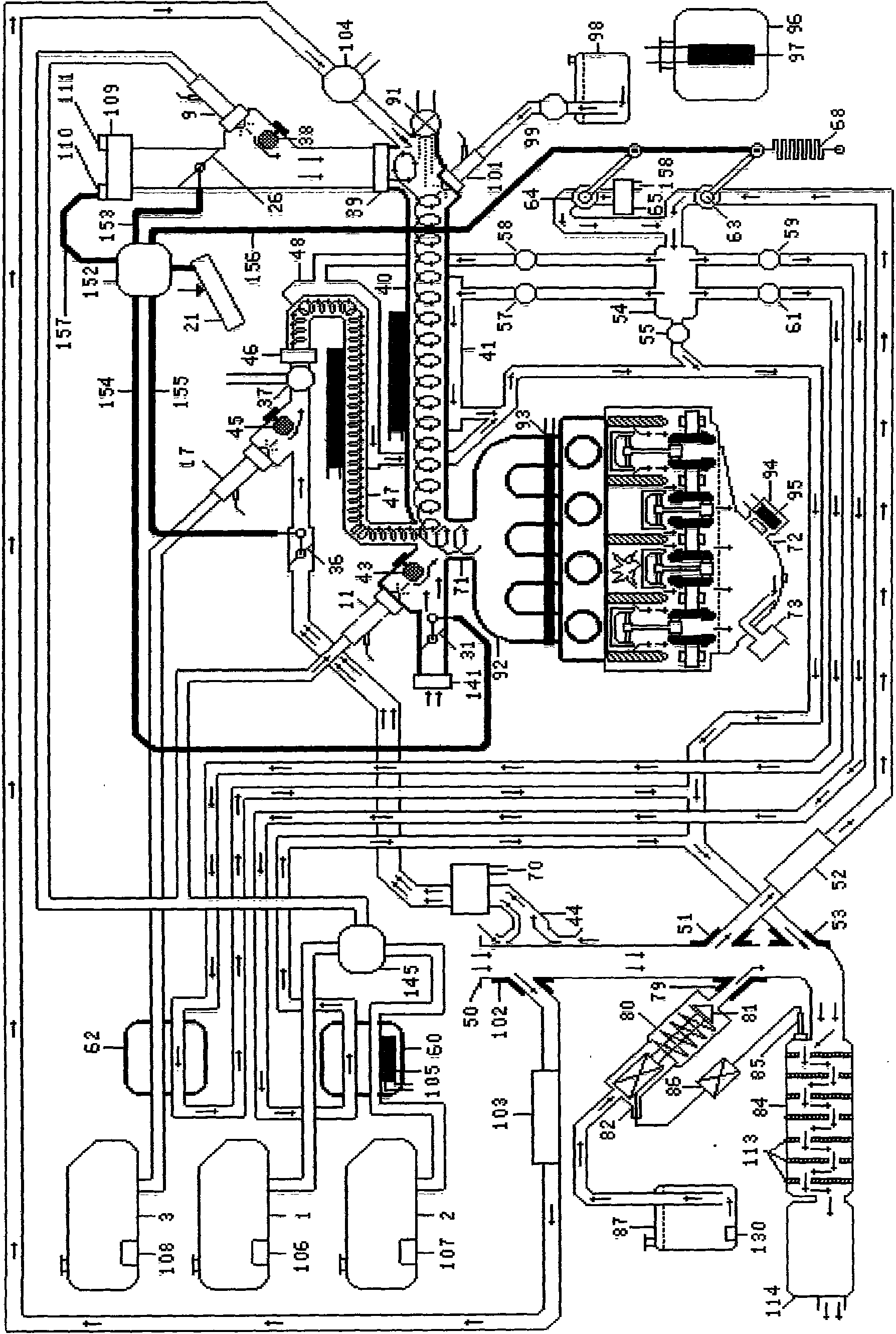
[0058] Embodiment 1: a kind of internal-combustion engine energy-saving and emission-reduction system is characterized in that said internal-combustion engine energy-saving and emission-reduction system (see figure 1 , figure 2 , Figure 5 ) includes an internal combustion engine, a temperature-regulating mineral fuel tank 1 and a thick long pipe swirl fine unit, said thick long pipe swirl fine unit is composed of a gas forced thinning long pipe 40 and a first fuel gas forced thinning long pipe 40 input end A swirl generator 39 is formed, and the output end of said temperature-regulating mineral fuel tank 1 is respectively connected to the input end of the gas forced thinning long pipe 40 and the input end of the intake pipe of the internal combustion engine, forming a far-near cooperation fuel supply unit; The output end of the forced thinning long pipe 40 of the fuel gas is connected to the intake manifold 71 of the internal combustion engine, and the intake manifold 71 i...

Embodiment 2

[0087] Embodiment 2: a kind of internal combustion engine energy saving and emission reduction system (see Figure 4 ), change the fuel switching valve 145 in Embodiment 1 into a fuel supply switching valve 4, that is, the output end of the fuel supply switching valve 4 is connected to the input end of the fuel main pipe 7 according to the fuel delivery pump 6, and the output ends of the fuel main pipe 7 are respectively according to The main fuel injector and starting fuel injector 9 is connected to the input end of the gas forced thinning long pipe 40, and the increasing fuel injector 11 is connected to the intake main pipe 71, and the fuel pressure regulator 8 is respectively connected to the regulator through the fuel return steering valve 5. The return end of the warm mineral fuel tank 1 and the return end of the temperature-regulating bio-fuel tank 2; other parts are the same as in Embodiment 1.

Embodiment 3

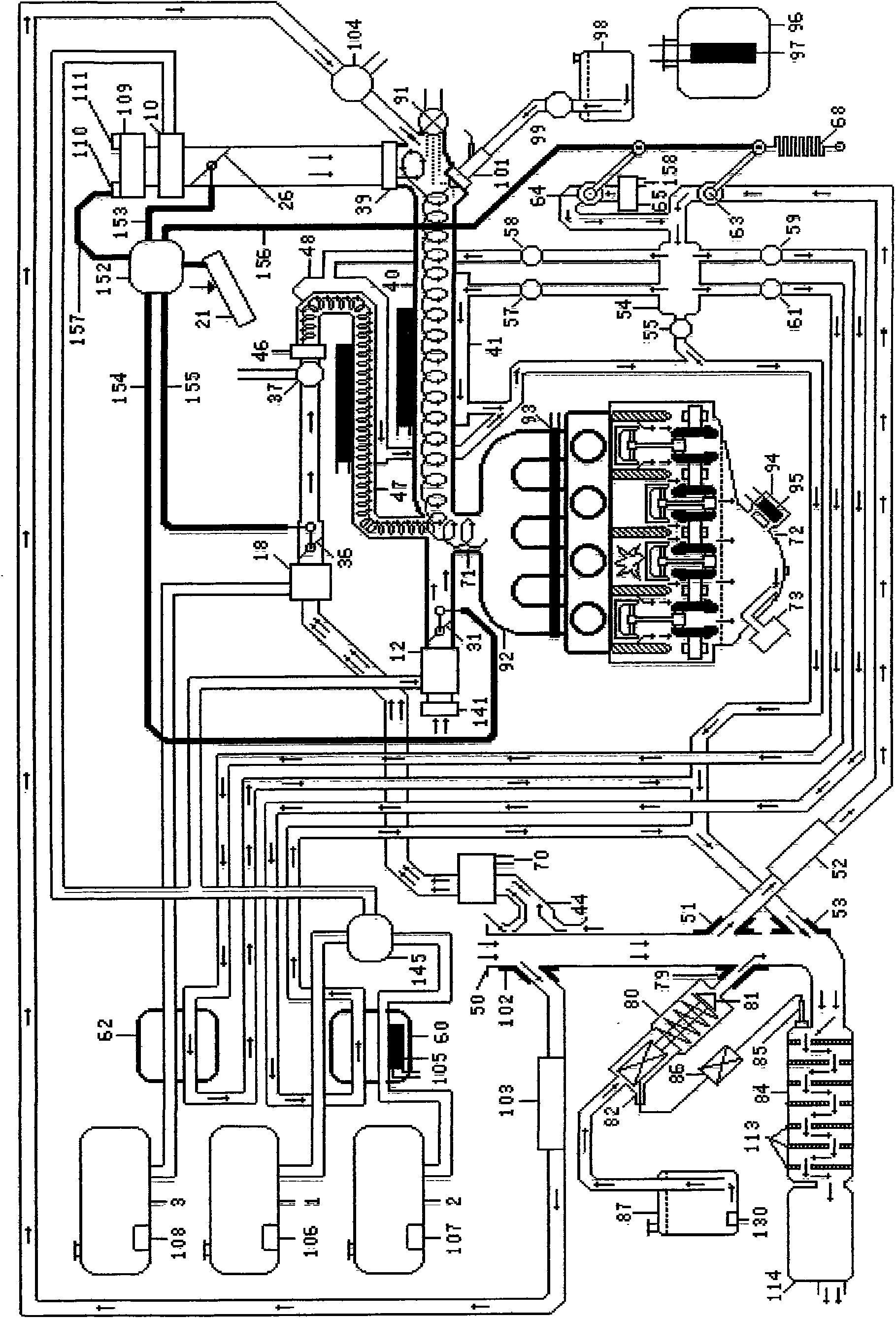
[0088] Embodiment 3: a kind of internal combustion engine energy saving and emission reduction system (see image 3 , Figure 6 ), change the main fuel injector and starting fuel injector 9 in Embodiment 1 into the main carburetor 10, that is: the output end of the temperature-adjusting mineral fuel tank 1 is connected to the input end of the fuel delivery pump 6, and the fuel delivery pump 6 The output ends of the fuel switch valve I 145-a are respectively connected to the main carburetor 10, and the fuel switch valve II 145-b is connected to the main carburetor 12 to connect to the intake manifold 71; The input end of the bio-fuel delivery pump 142 and the output end of the bio-fuel delivery pump 142 are respectively connected to the main carburetor 10 through the fuel switching valve I 145-a, and connected to the carburetor 12 through the fuel switching valve II 145-b. Gas main pipe 71; said main carburetor 10 is connected to the input end of gas forced thinning long pipe ...


PUM


Abstract

The invention relates to an engine energy-saving and emission-reducing system coordinated by a heat pipe and a cold pipe, which comprises an energy-saving and emission-reducing system of an internal combustion engine and the energy-saving and emission-reducing system of an external combustion engine, wherein, the energy-saving and emission-reducing system of the internal combustion engine comprises the internal combustion engine, a temperature-conditioning mineral fuel tank and a thick long swirling flow thin unit; and the energy-saving and emission-reducing system of the external combustion engine comprises the external combustion engine, a temperature-conditioning blending water tank and a water gas forced thinned long pipe. The working method comprises the working method of the energy-saving and emission-reducing system of the internal combustion machine and he working method of the energy-saving and emission-reducing system of the external combustion machine. The system has the advantages that the principle is simple and easy to develop and most of parts can directly select the existing standard parts for being used after simple transformation of the parts; the aggregate role of various technologies can sufficiently thin mixed gas, greatly reduce working temperature, improve the key technology which can greatly improve the geometric compression ratio and lead an oil-saving index to be about 50%; and the various technologies can be comprehensively applied for obtaining the energy-saving and emission-reducing ultra-high index, and the single technology therein can be independently used for obtaining the medium energy-saving and emission-reducing index with a small amount of investment.

Description

(1) Technical field: [0001] The invention belongs to the field of industrial technical equipment for an engine to obtain kinetic energy and heat energy through fuel combustion, in particular to a method and system for energy-saving and emission-reduction of an engine that uses heat pipe and cold pipe mechanisms to program multiple technologies and burn with water, that is, a heat pipe The engine energy saving and emission reduction system coordinated with the cold pipe and its working method are referred to as "heat pipe" technology. (2) Technical background: [0002] Fossil fuels will be exhausted sooner or later. Therefore, a variety of renewable fuels have been developed in the energy field. Because the molecular composition of these new energy products is different from that of fossil energy, the technical indicators cannot be completely consistent with those of fossil energy, so there are some incompatibility. Problems, such as poor startability, poor fluidity, and low ...

Claims


Application Information

Patent Timeline
Patent Type & Authority Applications(China)
IPC IPC(8): F02G1/043F02D19/08F02M25/035F01M11/00F01N3/08
CPCY02T10/16Y02T10/12
Inventor 段洪池李庄石柱国曹津宏
Owner 段洪池
Why Eureka
Try Eureka