
High fuel efficiency flywheel and cylinder internal cambustion engine hybrid (abbreviated as F&C engine hybrid)

a technology of cylinder internal cambustion and high fuel efficiency, which is applied in the direction of machines/engines, couplings, transportation and packaging, etc., can solve the problems of not being able to overcome, not using the effective arm, not improving the pressure distribution and the effective arm being bigger

Inactive Publication Date: 2008-11-13
WANG TSE CHENG +1
View PDF8 Cites 7 Cited by
  • Summary
  • Abstract
  • Description
  • Claims
  • Application Information

AI Technical Summary

Benefits of technology

[0202]2. The F&C engine is no inherent faults as the mentioned engines, it can use the effective arm plenty, to reduce rpm, the pairs of peak and valley can replace the cylinders of the engine, that is reduced cylinders of the engine. The rpm comes from the fuel; the effective arm is made of a piece of steel, the fuel is consumed very easy; to consume the steel needs a longer time; in F&C engine, between the parts to parts or device to device are adjustable, so, its fuel efficiency can be made as higher as around 70%, or more, that may approach the goal 100 mpg. The advantages of the F&C engine are that in low rpm. can give big torque and horse power; the structure is much simpler than the mentioned engines, it can save fabricating cost;

Problems solved by technology

1. In accordance with the above statements, we understand obviously that we can not to overcome the inherent faults, especially, it can not use the effective arm plenty, and the match of the effective arm and the force better, in the reciprocating engine; and can not improve the pressure distribution and the effective arm bigger, in rotary engine.
So, we can not make the fuel efficiency higher of this engines, the mentioned engines have to be replaced by F&C engine.

Method used


Image

  • High fuel efficiency flywheel and cylinder internal cambustion engine hybrid (abbreviated as F&C engine hybrid)
  • High fuel efficiency flywheel and cylinder internal cambustion engine hybrid (abbreviated as F&C engine hybrid)
  • High fuel efficiency flywheel and cylinder internal cambustion engine hybrid (abbreviated as F&C engine hybrid)

Examples


Embodiment Construction

[0028]The figures:

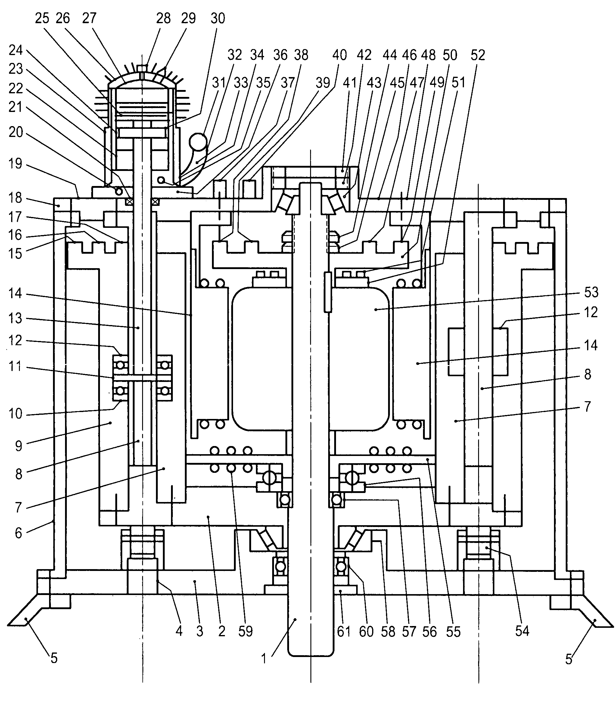
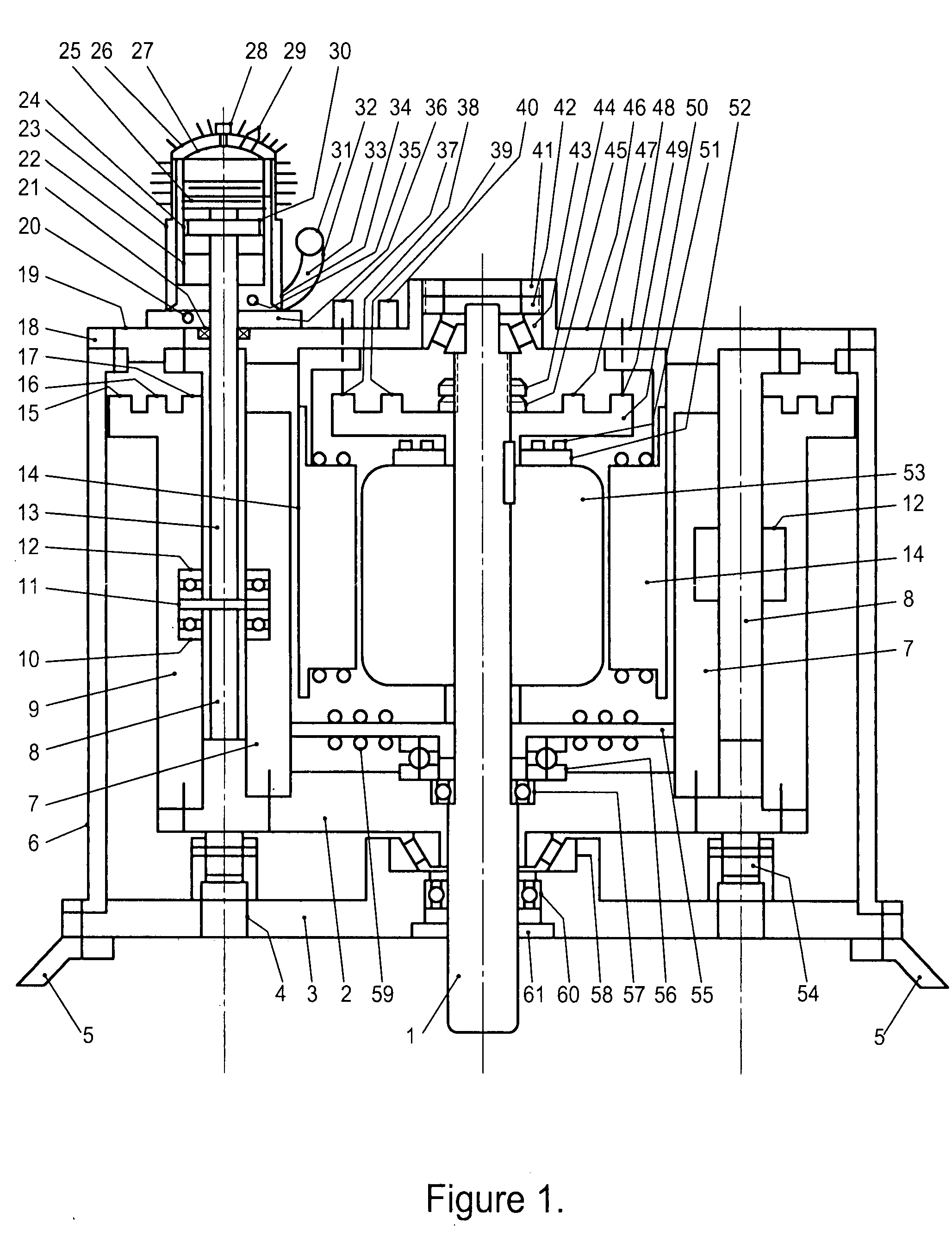
[0029]FIG. 1. is the vertical section of the hybrid.

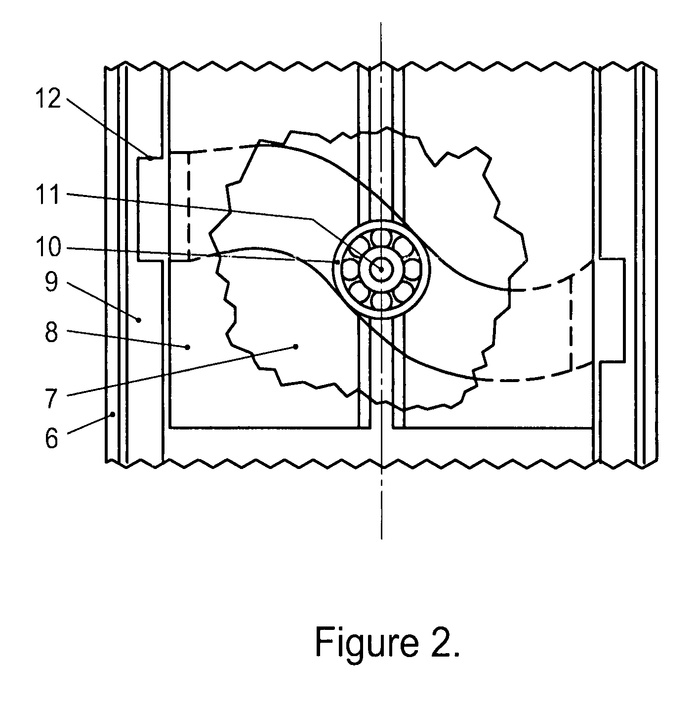
[0030]FIG. 2 is the peeled section of the channel inclined surface, the bearings and pin.

[0031]The attached figures.

[0032]The descriptions with the numbered embodiments (please to make a reference to FIG. 1.):

THE DESCRIPTION

[0033]Numbers:[0034]1. The central axle: it bears the parts: the cylindrical cam (flywheel, it constructed of the parts in item 2); 55.magnetic clutch;58. armature;50.driving plate.[0035]2. The bottom plate of the cylindrical cam: it mounted with 7.inner wall, 9. the outer wall with flange, 56.thrust bearing.57.overdrive clutch.[0036]3. Bottom plate of the engine case: it mounted 54.supporting rollers 58. Bevel roller bearing.60 roller bearing, 61.oil seal.[0037]4. The connecting bolts.[0038]5. The foot.[0039]6. The tube of the engine case.[0040]7. The inner wall that mounted on the 2.bottom plate of cylindrical cam.[0041]8. The channel guiding plate mounted on the 18. upper plate of the engin...


PUM


Abstract

F&C engine includes a central shaft mounted a cylindrical cam, that formed with two pieces of different diameter steel tubes, as the inner and outer walls, the upper end of the outer wall, placed a driving flange, to drive the engine timing devices. on the two layer walls (for light duty or small engine the single layer wall is acceptable) with pairs of peak and valley channel, a overdrive clutch; inside the cam contained a dynamotor to form a hybrid; a magnetic clutch, for engaging or disengaging the cylindrical cam; a driving plate for driving the devices that not related to the engine timing; a cylinder to produce power and transfer the power to the cam through a push rod; a guide plate to guide the push rod; many support rollers for supporting the cam; a tubular case with foot for contain and support the engine.

Description

BACKGROUND OF THIS INVENTION[0001]Since more than 100 years of times, people are perplexed by how to raise the fuel efficiency of the internal combustion engines. In the present time, the shortage of petrol-oil, the pollution of environment, the green house effect and weather change that becomes warmer and warmer. Such effects are a part from the emissions of our everyday popular used of the very low fuel efficiency internal combustion engines, such as the cars, ships and heavy duty equipments etc. Some bodies have clamoring to decrease the co2, In such a case, It really need an higher fuel efficiency engine to solve the very important problems of the world urgently. If we can invent a new engine, that can eliminate the causes, that makes the fuel efficiency is very low of the reciprocating and rotary (Wankel's) engines, a part of the dilemmas of the world will be reduced.[0002]By a long time to study and research, I have been discovered the real causes, that makes the very low effi...

Claims


Application Information

Patent Timeline
IPC IPC(8): F02B75/06F16D3/10
CPCB60K6/105F01B3/0032F01B3/0052F01B9/06Y10T74/2121H02K7/075H02K7/1815Y02T10/6204F02B73/00Y02T10/62
Inventor WANG, TSE-CHENGWANG, MING
Owner WANG TSE CHENG
Learn More