
Vehicle drivetrain system

a technology of drivetrain and drive wheel, which is applied in the direction of fluid gearing, transportation and packaging, gearing, etc., can solve the problems of less torque transferred to the drive wheel, increased strain on the drivetrain components, and lower engine rpm at cruising speed of the vehicle, so as to improve the fuel economy of the vehicle and reduce the torque presen

Active Publication Date: 2020-06-23
WANKE MATTHEW T
View PDF12 Cites 0 Cited by
  • Summary
  • Abstract
  • Description
  • Claims
  • Application Information

AI Technical Summary

Benefits of technology

This patent is about a new vehicle system that improves fuel economy and reduces emissions. It does this by controlling the amount of torque in the engine and transferring it to the wheels. The system also uses special gear ratios to optimize engine speed and rear end performance. This allows the vehicle to maintain a desired speed at lower engine speeds, which improves fuel economy and increases the lifespan of its components. Additionally, the system can be used with a conventional combustible engine and has the ability to improve vehicle speed and efficiency.

Problems solved by technology

One issue with the aforementioned is the increased strain on the drivetrain components.
These low gear ratios result in a lower engine RPM at cruising speed of the vehicle but also result in less torque transferred to the drive wheel.
One major issue with utilizing the aforementioned gear ratio to achieve a lower engine RPM is the torque remains in the drivetrain components and as such results in broken u-joints and other component failure.
Having conventional transmission ratios and rear end gears can result in an increase fuel consumption under certain conditions.
When a driver encounters more adverse conditions such as steep roads or high winds, the driver will apply more accelerator to maintain vehicle speed which results in lower fuel economy.

Method used


Image

  • Vehicle drivetrain system
  • Vehicle drivetrain system
  • Vehicle drivetrain system

Examples


Embodiment Construction

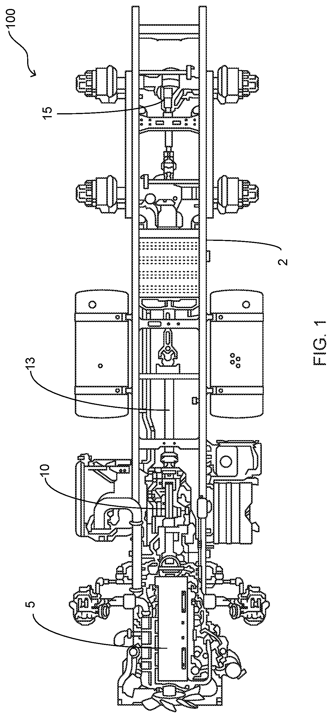
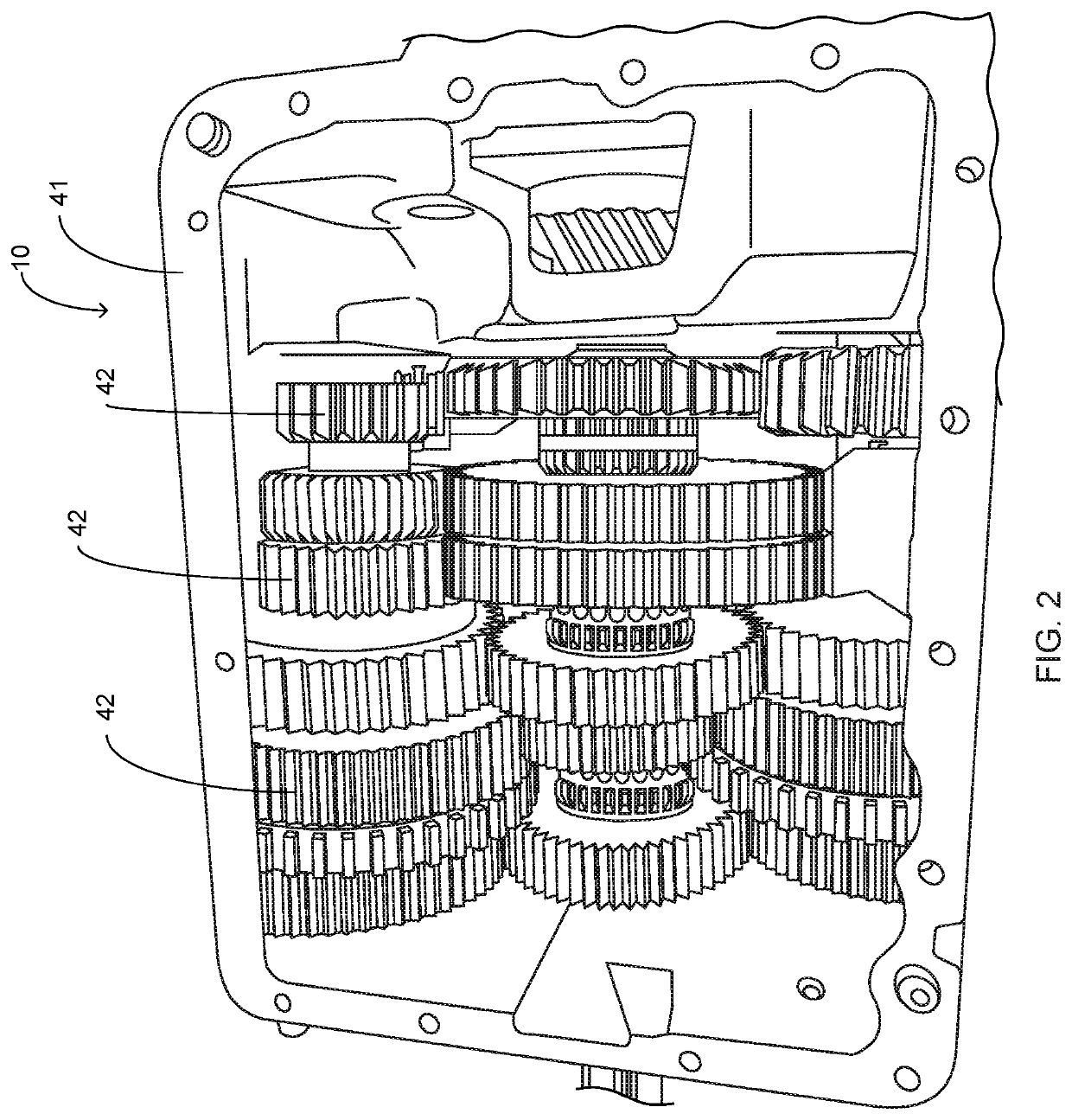
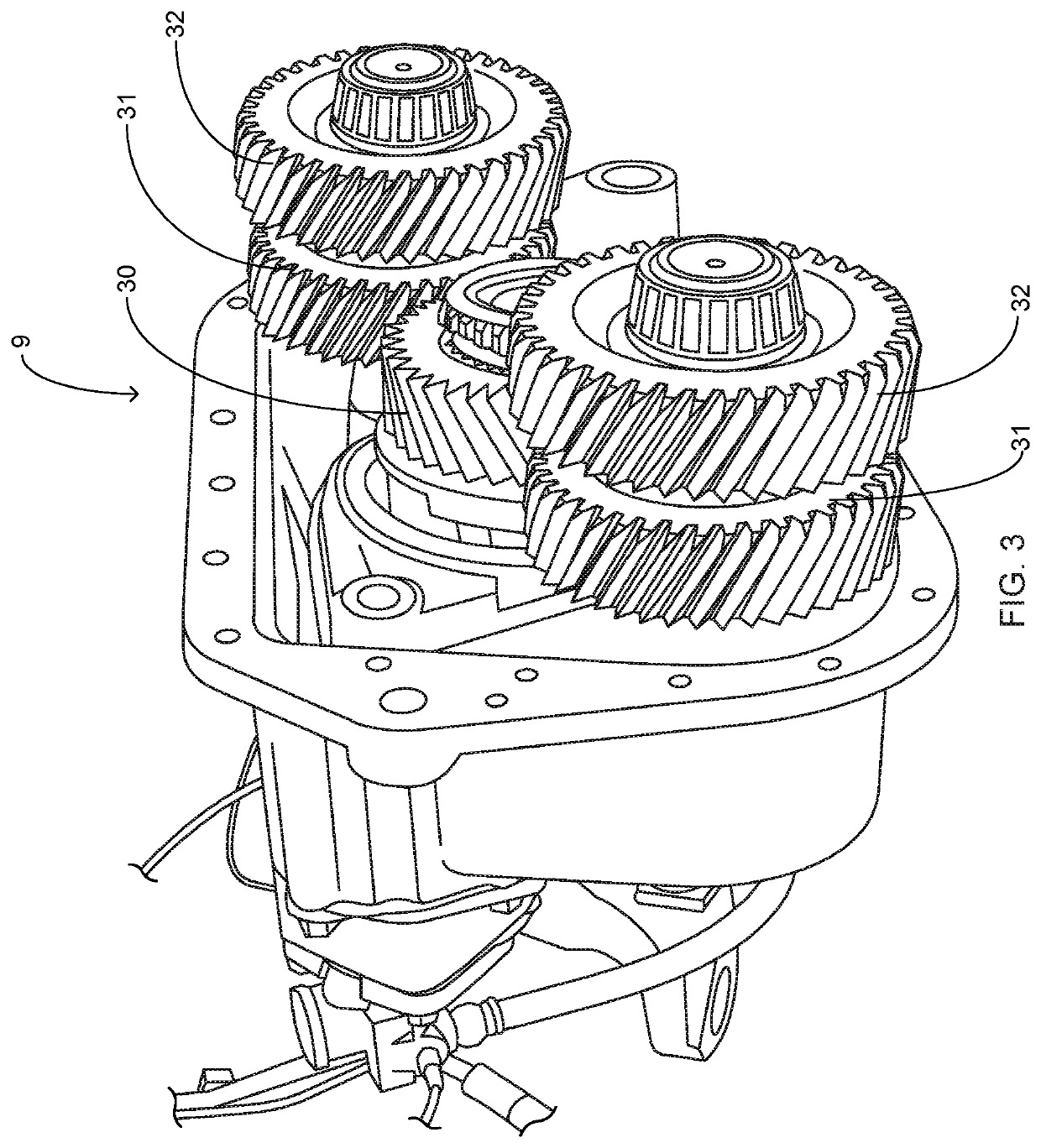
[0019]Referring now to the drawings submitted herewith, wherein various elements depicted therein are not necessarily drawn to scale and wherein through the views and figures like elements are referenced with identical reference numerals, there is illustrated a vehicle drivetrain system 100 constructed according to the principles of the present invention.

[0020]An embodiment of the present invention is discussed herein with reference to the figures submitted herewith. Those skilled in the art will understand that the detailed description herein with respect to these figures is for explanatory purposes and that it is contemplated within the scope of the present invention that alternative embodiments are plausible. By way of example but not by way of limitation, those having skill in the art in light of the present teachings of the present invention will recognize a plurality of alternate and suitable approaches dependent upon the needs of the particular application to implement the fu...


PUM


Abstract

A drivetrain assembly for a motor vehicle such as a tractor-trailer rig wherein the drivetrain assembly includes a transmission and a rear end differential that have gearing operable to lower the operational engine RPM's of the vehicle. The transmission of the present invention includes a gearing ratio having a stepped percentage difference intermediate each gear. The final gear ratio of the transmission ranges between 0.47 to 1 and 0.63 to 1. A rear end gear ratio is present within the range of 3.08 to 1 to 3.90 to 1. The rear end gear ratio is approximately five and a half to six and a half greater than the ratio of the final gear of the transmission. The engine RPM's of the vehicle are at a lower RPM when the transmission is in its final gear or speed resulting in less fuel injection cycles and improved fuel economy.

Description

FIELD OF THE INVENTION[0001]The present invention relates generally to vehicle drivetrain assemblies, more specifically but not by way of limitation, a drivetrain assembly for a larger vehicle such as but not limited to a tractor trailer wherein the components of the drivetrain system of the present invention are configured to provide operation of the motor at a lower RPM so as to improve fuel economy while maintaining the engine torque transfer to the drive wheels.BACKGROUND[0002]Millions of tractor-trailer rigs are operated on the roads everyday. These large vehicles are a primary source of logistics for all types of goods and products and are capable of handling large loads. The average fuel economy for a tractor-trailer vehicle is about six miles per gallon. Fuel costs is one of the most significant categories in operating a tractor-trailer vehicle. Many attempts have been made to optimize fuel consumption in order to reduce the overhead costs of operating a tractor-trailer vehi...

Claims


Application Information

Patent Timeline
IPC IPC(8): F16H37/08F16H47/04F16H57/037F16H57/02B60W10/06
CPCF16H57/037F16H47/04F16H37/082F16H2057/02017F16H2057/02043B60W10/06B60Y2200/221F16H2057/02069B60K17/165B60Y2200/145F16H3/30F16H2037/045F16H2057/02056F16H2200/0069
Inventor WANKE, MATTHEW T.
Owner WANKE MATTHEW T
Learn More