Climate control system and motor actuator therefor

a technology of motor actuators and climate control systems, applied in the direction of motor/generator/converter stoppers, dynamo-electric converter control, instruments, etc., can solve the problems of increasing complexity, adding to expenses, unduly expensive motor actuators

Inactive Publication Date: 2005-02-24
HELLA ELECTRONICS +1
View PDF12 Cites 24 Cited by
  • Summary
  • Abstract
  • Description
  • Claims
  • Application Information

AI Technical Summary

Problems solved by technology

A problem that arises from use of electric motors for changing positions of dampers is that the motors do not automatically stop when their dampers reach desired positions set by the hand-controlled elements.
One problem is that each motor actuator must include a rheostat-type, or potentiometer-type, component, which makes the motor actuator unduly expensive.
Further, such a system often requires five wires between the control head and the motor actuator, again increasing complexity and adding to expenses.
However, the system of FIG. 3 suffers from a number of other disadvantages.
One problem is that the back EMF pulse counter 34 is a rather complicated and specialized device that must be manufactured by a specialized manufacturer.
Further, the accuracy of such a back EMF pulse counter 34 is adversely affected by the erratic nature of back EMF.
In addition, the wearing of motor power brushes, and varying torque loads, can adversely affect a back EMF pulse count.
Similarly, starting and stopping transients can cause improper counts.
Further, this system is often prone, over time, to get out of calibration as mistakes are introduced into its back EMF pulse count.

Method used


Image

  • Climate control system and motor actuator therefor
  • Climate control system and motor actuator therefor
  • Climate control system and motor actuator therefor

Examples


Embodiment Construction

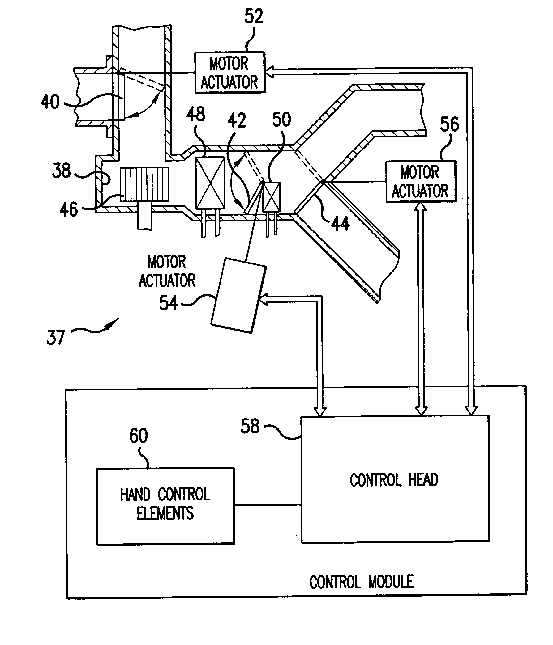
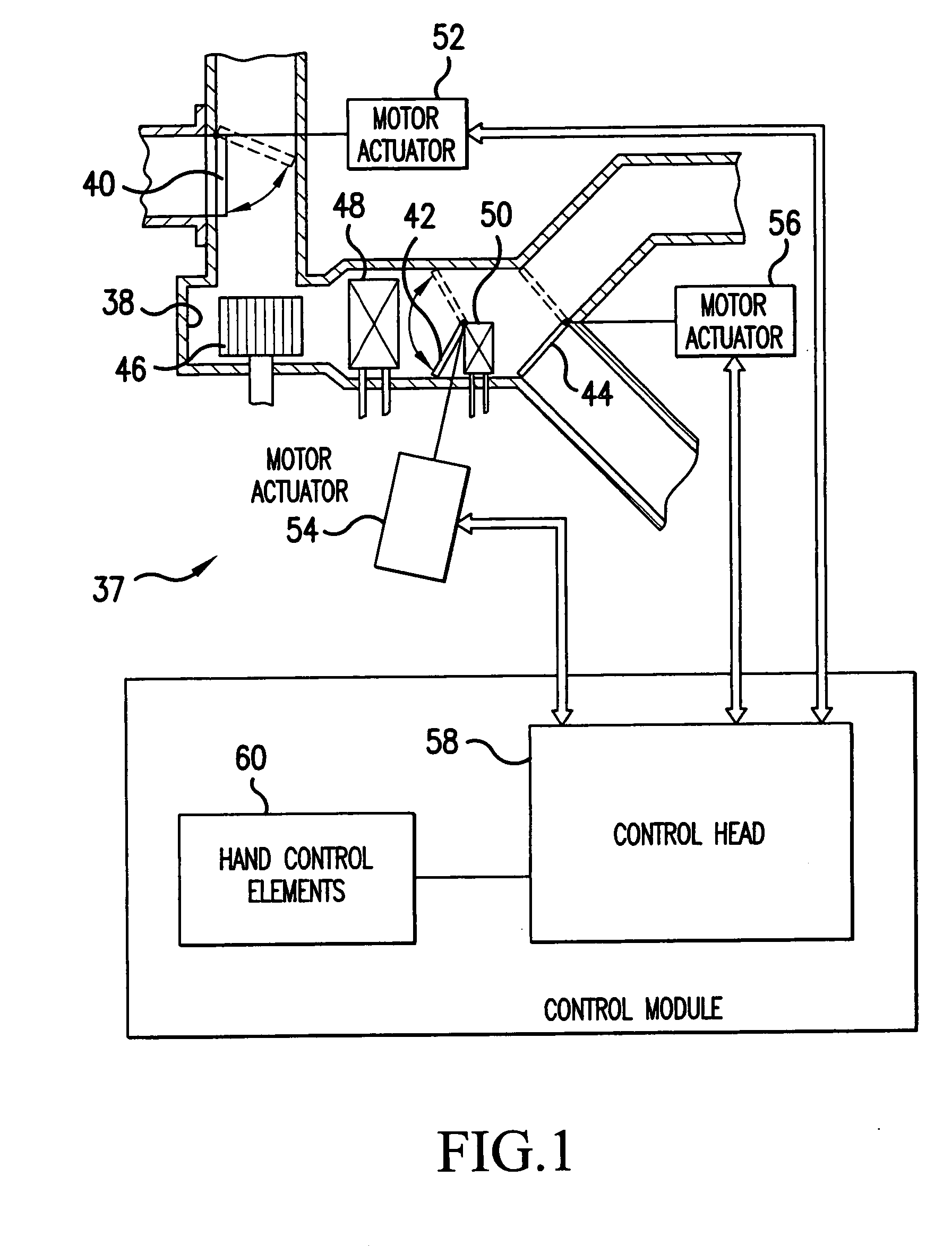
[0026]FIG. 1 depicts an automotive climate control system 37, otherwise known as a heating, ventilation and air-conditioning (HVAC) system that includes air passages 38 for channeling airflow. Positioned in these air passages 38, for example, are dampers 40, 42 and 44, a blower 46, an evaporator 48, and a heater core 50. The damper 40 is a recirculated / fresh-air selecting damper while the damper 42 is an air-mix damper, which determines how much air passes through the heater core 50. The damper 44 is a mode-selector damper that determines whether air is fed into a vehicle cab from up high or from down low, for example. It should be understood that these dampers, passages, and other elements are provided only as examples for purposes of explaining this invention. The climate control system could have a completely different appearance, with other passages, elements and damper placements, and still be within the invention. Similarly, it should be understood that the climate control sys...


PUM


Abstract

A motor actuator of a climate control system includes an specialized electric motor with a motor housing enclosing an encoder ring on a motor shaft having a plurality of opposite encoder-segment sets with encoder brushes on the housing wiping the encoder ring and thereby forming an encoder circuit through opposite segments of the encoder-segment sets. The electric motor further includes power and encoder terminals positioned externally of the motor housing with at least one power terminal being electrically coupled to one of the power brushes and at least one encoder terminal being electrically coupled to one of the encoder brushes. A control head of the system includes a continuity pulse counter coupled to the at least one encoder terminal for creating pulses representative of impedance in the encoder circuit and, therefore, movement of the motor shaft and a damper linked thereto.

Description

[0001] This application is a Divisional of co-pending application Ser. No. 10 / 645,515, filed on Aug. 22, 2003, and for which priority is claimed under 35 U.S.C. § 120; the entire contents of which are hereby incorporated by reference.BACKGROUND OF THE INVENTION [0002] This application relates generally to climate control (heating, ventilating and air-conditioning, or HVAC) systems, especially to those used for motor vehicles, and more specifically to motor actuators therefor and electric motors for such actuators. [0003] Climate control systems, particularly those for motor vehicles, normally include air passages having movable dampers therein to control airflow through the passages. The movable dampers are usually moved by hand-manipulating hand-controlled elements. In this respect, an operator manipulates one of the hand-controlled elements to move one or more of the dampers to a respective desired position for achieving a desired airflow pattern in the passage(s). In the past, th...

Claims


Application Information

Patent Timeline
Patent Type & Authority Applications(United States)
IPC IPC(8): B60H1/00B60L1/02G05B5/00H02K23/66H02PH02P1/00
CPCB60H1/00835B60L1/02H02K23/66Y02T10/64
Inventor JASINSKI, RICHARDRICHTER, RALF
Owner HELLA ELECTRONICS
Why Eureka
Try Eureka