Display system and electronic appliance including the display system

a display system and electronic appliance technology, applied in the field of displays, can solve the problems of not being able to meet the essential function of the display to display images and information, not being able to clearly and suitably recognize display contents, and having problems described in conventional displays, so as to improve viewability and reduce size and cost

Inactive Publication Date: 2005-02-24
PIONEER CORP
View PDF7 Cites 55 Cited by
  • Summary
  • Abstract
  • Description
  • Claims
  • Application Information

AI Technical Summary

Benefits of technology

[0009] In view of the above described problems, an object of the present invention is to provide a display sy...

Problems solved by technology

The conventional displays, however, have problems described below.
Thus, there is a technical problem that it is difficult or impossible to clearly and suitably recognize display contents, depending on the condition of the display contents (e.g., high-definition).
That is, there is a problem that the essential function of the display to display ...

Method used


Image

  • Display system and electronic appliance including the display system
  • Display system and electronic appliance including the display system
  • Display system and electronic appliance including the display system

Examples


examples

[0086] Some examples of the display system according to the present invention will be described with reference to the drawings.

first example

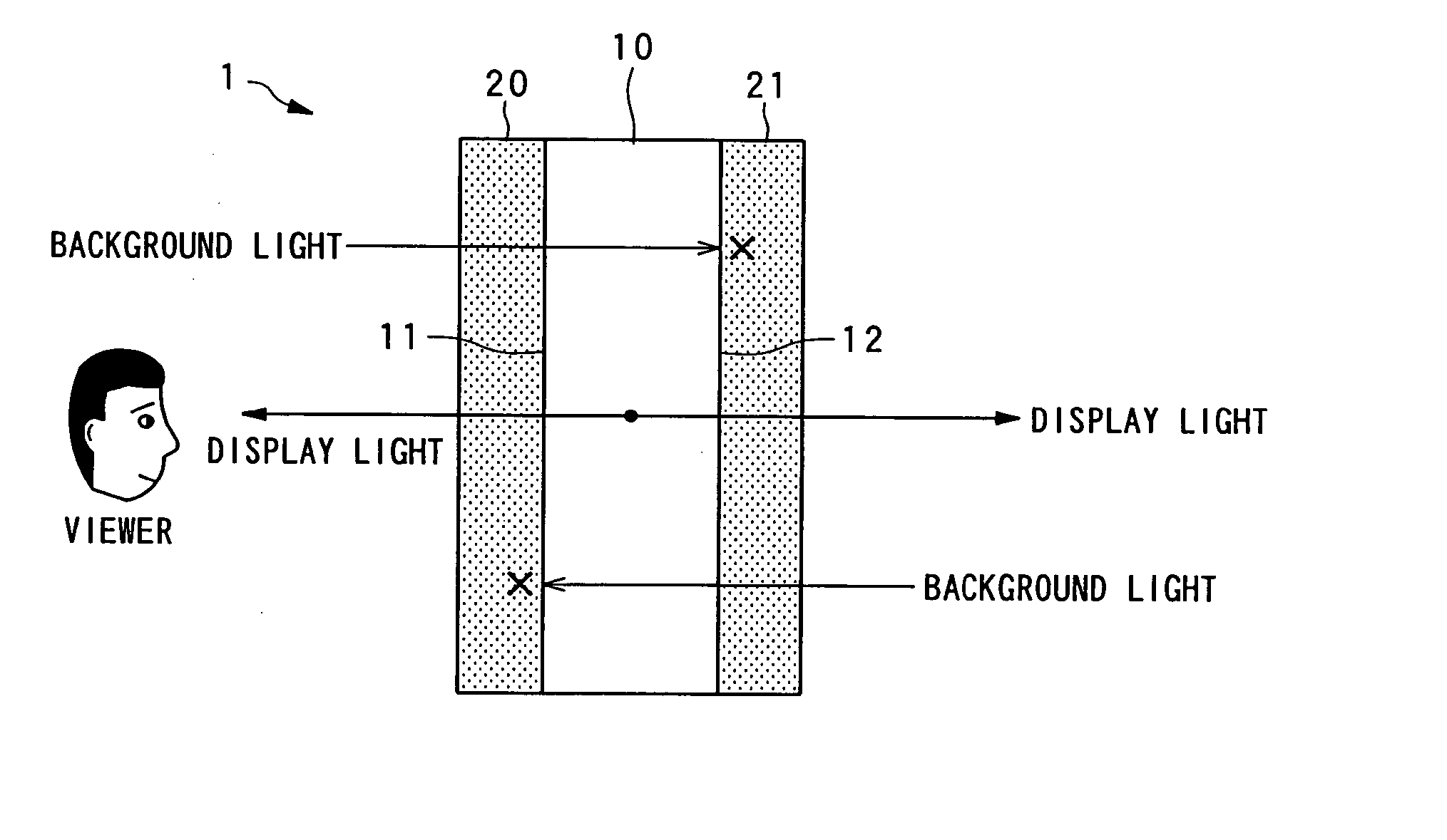
[0087] A display system in the first example of the present invention will be described with reference to FIGS. 1 to 6. In the display system in the first example of the present invention, a display unit, which is an example of “display device” in the present invention, is placed between two polarizing plates, which are an example of the light transmission control device in the present invention.

[0088] Basic Construction

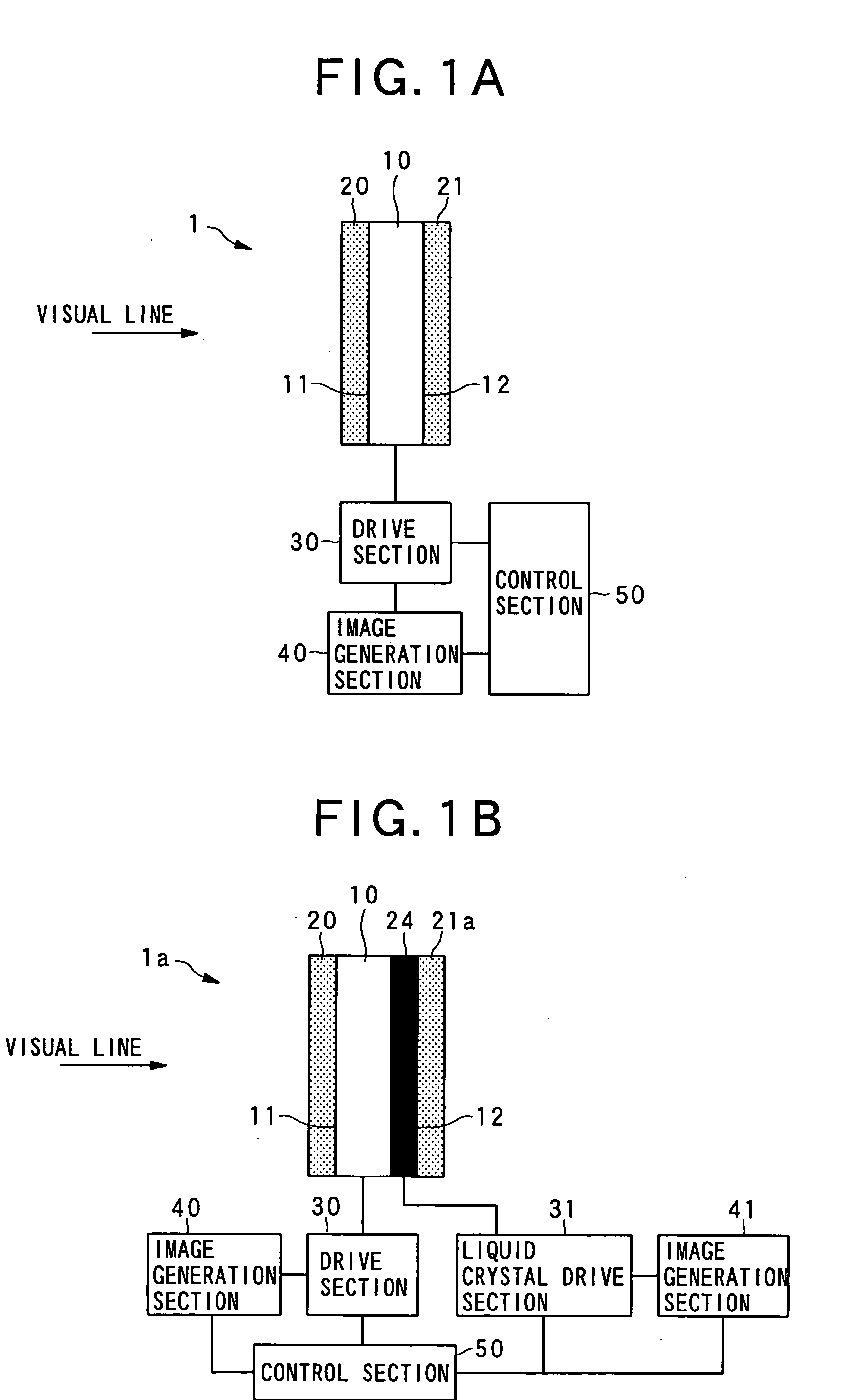
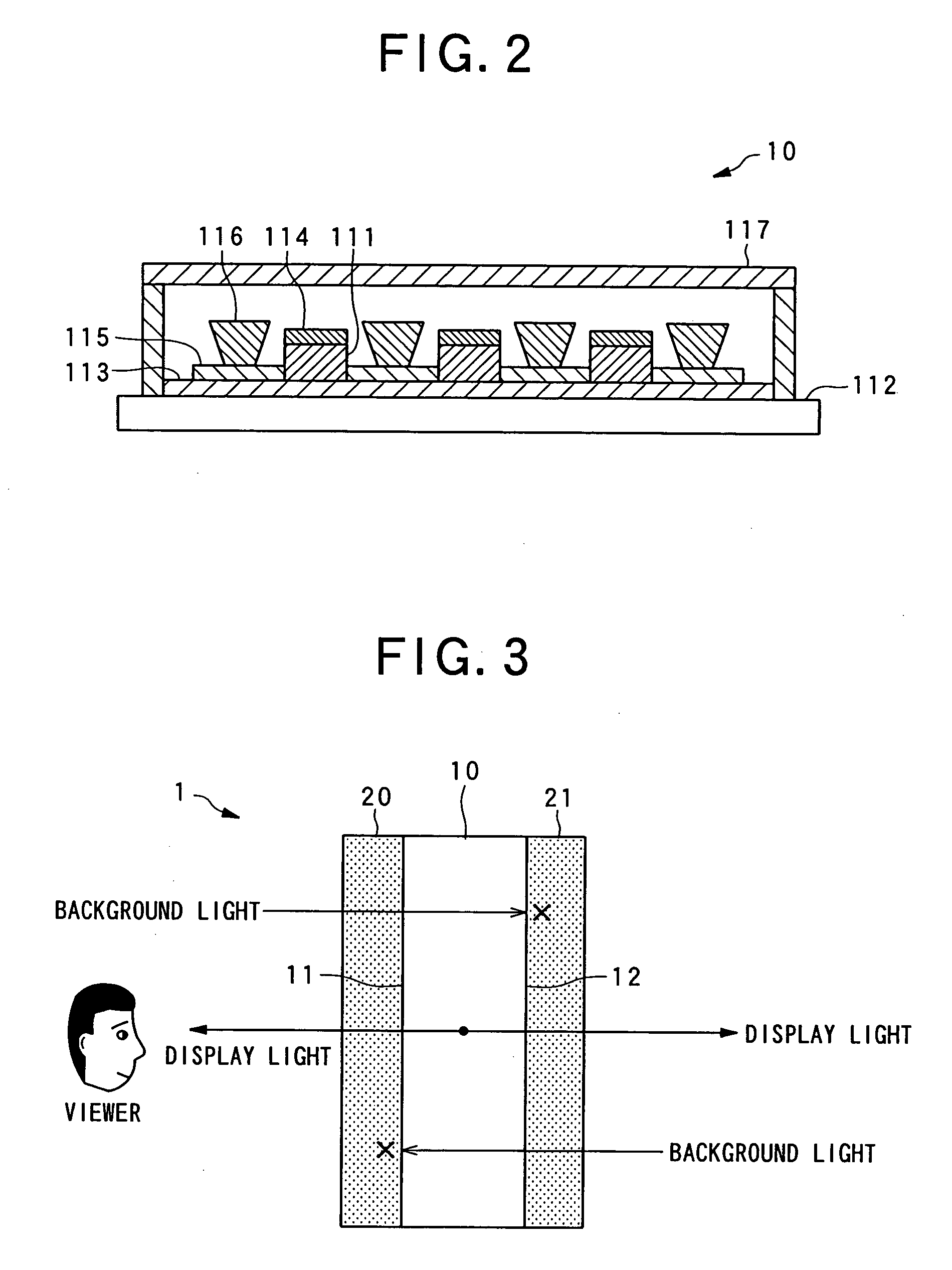
[0089] The basic construction of the display system in the first example of the present invention will be described with reference to FIGS. 1 to 2. FIG. 1A is a block diagram schematically showing a basic construction of the display system in the first example; FIG. 1B is a block diagram schematically showing another basic construction of the display system in the first example; and FIG. 2 is a cross-sectional view schematically showing details of the construction of a display device in the display system in the first example.

[0090] As shown in FIG. 1A, the displa...

concrete examples

[0129] Concrete examples of use as concrete products (e.g., portable telephone) of the display system 1 in the first example and the display system 2 in the example modified from the display system 1, will be described with reference to FIGS. 8 and 9. FIGS. 8A, 8B, and 8C are diagrams chematically showing a portable telephone having the display system 1, and FIGS. 9A and 9B are diagram schematically showing a portable telephone having the display system 2.

[0130] As shown in FIG. 8A, in the portable telephone 201 having the display system 1 in the first example, display contents are suitably displayed on a main display corresponding to the first image display surface 11 at the time of normal telephone conversation or button operation. At this time, an image formed by reversing the image displayed on the first image display surface 11 is displayed on a sub display (i.e., a back display) corresponding to the second image display surface 12 as shown in FIG. 8B. Also, background transmi...


PUM


Abstract

A display system (1) having improved viewability and reduced in size and manufacturing cost has a display device (10) which includes an image forming layer (111) capable of emitting display light toward both front and back sides, and which can produce a display on a first surface (11) by a display light portion emitted toward the back side and produce a display on a second surface (12) at the back of the first surface by a display light portion emitted toward the back side. The display also has an optical transmission control device (20, 21) which is placed along at least one of the first surface and the second surface, and which can control transmission of at least one of background light from a position at the back of the second surface as viewed from the first surface side and background light from a position at the back of the first surface as viewed from the second surface side.

Description

BACKGROUND OF THE INVENTION [0001] 1. Field of the Invention [0002] The present invention belongs to the field of displays including spontaneous luminescence devices such as electroluminescent devices (hereinafter referred to as “EL” as required). [0003] 2. Description of the Related Art [0004] Various displays have been provided. For example, in addition to traditional displays such as movie projectors in which a film is fed to a position in front of a light projecting unit to display an image on a screen, and displays having a cathode ray tube (CRT), recent proposals include liquid crystal displays, plasma displays, electroluminescent devices and the like. These kinds of displays are used in appliances in which importance is mainly attached to the functions of displays (e.g., television sets), as well as in other various kinds of electronic appliances. For example, these kinds of displays are used by being incorporated in portable appliances for use as a personal terminal (persona...

Claims


Application Information

Patent Timeline
IPC IPC(8): H05B33/02G02F1/1335G09F9/00G09F9/30G09F9/40G09F9/46G09G3/20G09G3/30H01L27/32H01L51/50H04M1/02H05B33/12
CPCG02F1/1335G02F2001/133342H01L27/3232H01L27/3244H04M1/0266H04M1/0214H04M1/0225H04M1/0235H04M1/0245H01L2251/5323G02F1/133342H10K59/50H10K59/12H10K2102/3031
Inventor KURODA, KAZUO
Owner PIONEER CORP
Why Eureka
Try Eureka