Reflective liquid crystal display device having cholesteric liquid crystal color filter

Inactive Publication Date: 2005-02-24
LG DISPLAY CO LTD
View PDF13 Cites 14 Cited by
  • Summary
  • Abstract
  • Description
  • Claims
  • Application Information

AI Technical Summary

Benefits of technology

[0022] An advantage of the present invention is to provide a reflective liquid crystal display device of high display quality using a cholesteric liquid crystal color filter layer by reducing brightness at a boundary of a display region.
[0023] Another advantage of the present invention is to provide a reflective liquid crystal display device including a light shielding pattern corresponding to a cholesteric liquid crystal color filter layer at a non-display region of a lower substrate.
[0024] Additional features and advantages of the invention will be set forth in the description that follows, and in part will be apparent from the description, or may be learned by practice of the invention. The objectives and other advantages of the invention will be realized and attained by the structure particularly pointed out in the written description and claims hereof as well as the appended drawings.
[0025] To achieve these and other advantages and in accordance with the purpose of the present invention, as embodied and broadly described, a reflective liquid crystal display device includes: a first substrate including a display region and a first

Problems solved by technology

However, only about 7% of the light that is emitted by the backlight passes through each cell of the LCD device.
Since the backlight should emit light of a relatively high brightness, corresponding power consumption increases.
Moreover, use of the large capacity battery limits operating time.
On the other hand, because power consumption of the reflective LCD devices greatly decreases due to use of ambient light as a light source, operating time increases.
However, brightness of reflective LCD devices is very poor because the devices use only ambient light as a light source.
The poor brightn

Method used


Image

  • Reflective liquid crystal display device having cholesteric liquid crystal color filter
  • Reflective liquid crystal display device having cholesteric liquid crystal color filter
  • Reflective liquid crystal display device having cholesteric liquid crystal color filter

Examples


Example

[0040] Reference will now be made in detail to embodiments of the present invention, example of which is illustrated in the accompanying drawings. Wherever possible, the same reference numbers will be used throughout the drawings to refer to the same or like parts.

[0041]FIG. 6 is a schematic plan view of a reflective LCD device using a CCF layer according to an embodiment of the present invention. A boundary of a display region is shown in FIG. 6.

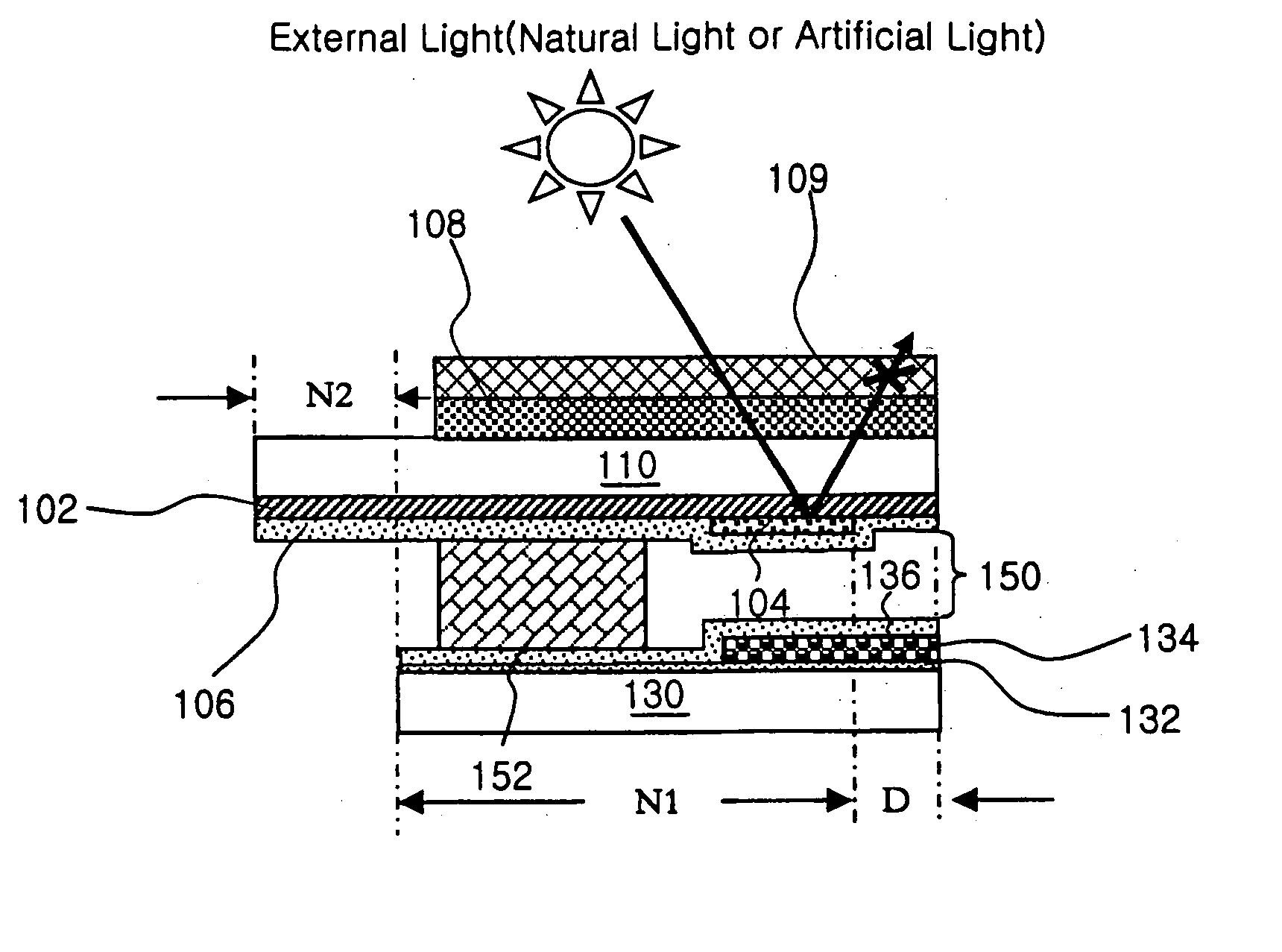
[0042]FIG. 6, a liquid crystal panel 160 includes a first substrate 110, a second substrate 130 smaller than the first substrate 110 and a liquid crystal layer 150 interposed between the first and second substrates 110 and 130. The liquid crystal panel 160 can be divided into a display region “D,” and first and second non-display regions “N1” and “N2” in plan view. The first non-display region “N1” is adjacent to a boundary of the display region “D” and is defined by the first and second substrates 110 and 130. The second non-display regi...


PUM


Abstract

A reflective liquid crystal display device includes a first substrate including a display region and a first non-display region, the first non-display region being disposed at a boundary of the display region. A second substrate faces and is spaced apart from the first substrate, the second substrate including a second non-display region corresponding to a portion larger than the first substrate. A light absorption layer is on an inner surface of the first substrate. A cholesteric liquid crystal color filter (CCF) layer is at the display region and the first non-display region is on the light absorption layer. A common electrode is on the CCF layer. An array element is on an inner surface of the second substrate. A light shielding pattern is on the array element, the light shielding pattern corresponding to the CCF layer at the first non-display region. A retardation plate and a polarizing plate are sequentially formed on the outer surface of the second substrate. A liquid crystal layer is interposed between the common electrode and the array element.

Description

[0001] This application claims the benefit of Korean Patent Application No. 2001-71519, filed on Nov. 16, 2001, which is hereby incorporated by reference as if fully set forth herein. BACKGROUND OF THE INVENTION [0002] 1. Field of the Invention [0003] The present invention relates to a liquid crystal display (LCD) device, and more particularly, to a reflective LCD device having a cholesteric liquid crystal (CLC) color filter. [0004] 2. Discussion of the Related Art [0005] Presently, LCD devices are developed as next generation display devices because of their light weight, thin profile, and low power consumption characteristics. In general, an LCD device is a non-emissive display device that displays images using a refractive index difference utilizing optical anisotropy properties of liquid crystal material that is interposed between an array (TFT) substrate and a color filter (C / F) substrate. Among the various type of LCD devices commonly used, active matrix LCD (AM-LCD) devices h...

Claims


Application Information

Patent Timeline
IPC IPC(8): G02F1/1333G02F1/1335
CPCG02F1/133512G02F1/133536G02F2001/133543G02F2001/133521G02F2001/133388G02F1/133388G02F1/133521G02F1/133543G02F1/1335
Inventor LEE, JOUN-HO
Owner LG DISPLAY CO LTD
Why Eureka
Try Eureka