Monitoring and response system

a technology of monitoring and response system, applied in emergency protective arrangements, switches, instruments, etc., can solve problems such as damage to windows, data loss and damage to electronic equipment, and potentially dangerous and/or harmful effects

Inactive Publication Date: 2005-02-24
STORM SHELTER
View PDF25 Cites 20 Cited by
  • Summary
  • Abstract
  • Description
  • Claims
  • Application Information

AI Technical Summary

Benefits of technology

[0013] Another feature of certain embodiments of this invention is to provide an intelligent monitoring and response system that may detect and locate certain conditions in a specific geographic area and cause devices within the area to automatically respond to the detected conditions.

Problems solved by technology

Environmental conditions can change suddenly, often with dramatic and potentially dangerous and / or harmful results.
Lightning strikes can result in data loss and damage to electronic equipment.
Excessive wind can damage windows.
Large snowfalls can result in avalanches and roof collapses.
Smog and other types of pollution can cause breathing problems.
Clearly, environmental changes, when unanticipated or unprepared for, have the potential to cause damage throughout geographic areas affected by the changes.
An important concern with these prior lightning protection devices is that control of the device is typically limited to detection of dangerous atmospheric conditions such as disclosed in the above-referenced patents.
Detection of dangerous atmospheric conditions at the precise location of the protection device may not be sufficient to protect the device from damage.
In addition, because electrical storms tend to cover a large geographic area and tend to move quickly, they are very difficult to detect based on one geographical data point.
Therefore, sensors located on protection devices may not have the range, sensitivity, or accuracy to detect distant atmospheric conditions that may still damage the equipment being protected.
Even if more sensitive sensors were employed, the cost of such an approach could be cost prohibitive.
Although lightning protection devices may permit users to manually disconnect equipment from external conductors, this is no different than merely unplugging the equipment.
Additionally, commercial users of such devices may be inconvenienced by having to have multiples of such units distributed throughout the building to protect a variety of electronic devices.
Likewise, a homeowner may be similarly inconvenienced by having to move about an entire house to trigger multiple devices attached to various outlets.
Such a system however may be undesirable because subscribers still must take affirmative action to protect themselves and / or their property from the imminent severe weather.
Manual triggering of the electrical circuit connection / disconnection devices may be desirable where certain structures interfere with lightning detection, thus rendering automated disconnection impractical; when normal sources of electrical power have failed; where dangerous, non-lightning related voltages may occur; when a user desires to have the protected equipment powered down; and when peace of mind or convenience dictates disconnection of the protected equipment.

Method used


Image

  • Monitoring and response system
  • Monitoring and response system
  • Monitoring and response system

Examples


Embodiment Construction

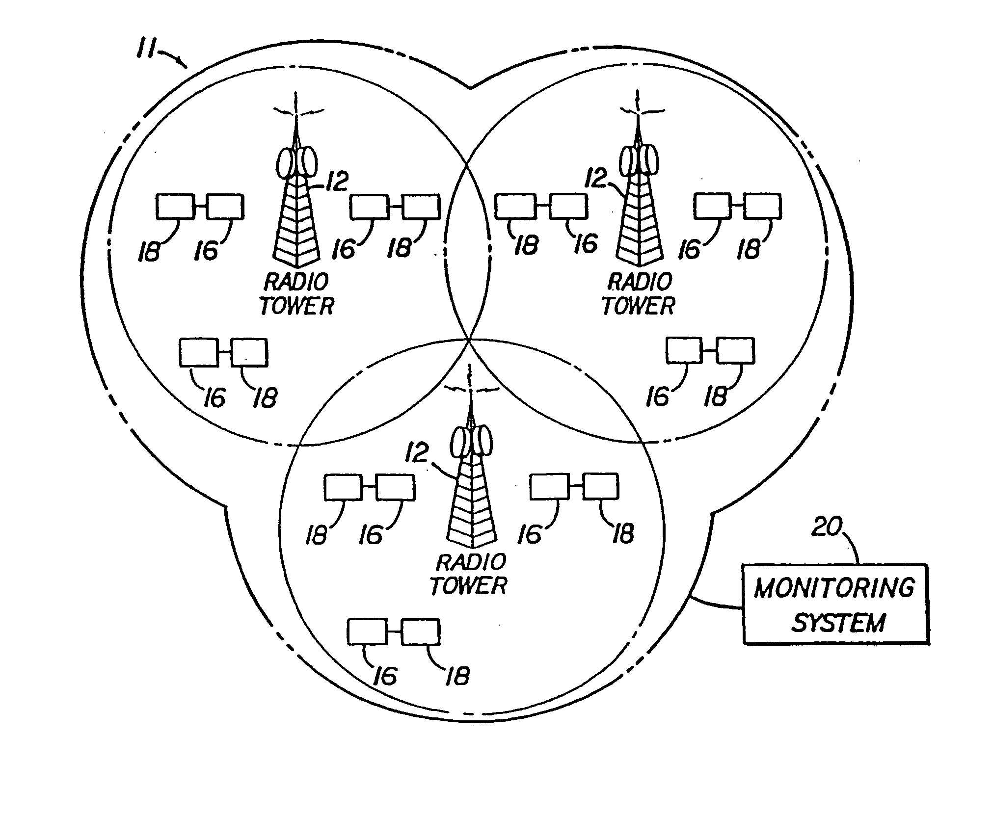
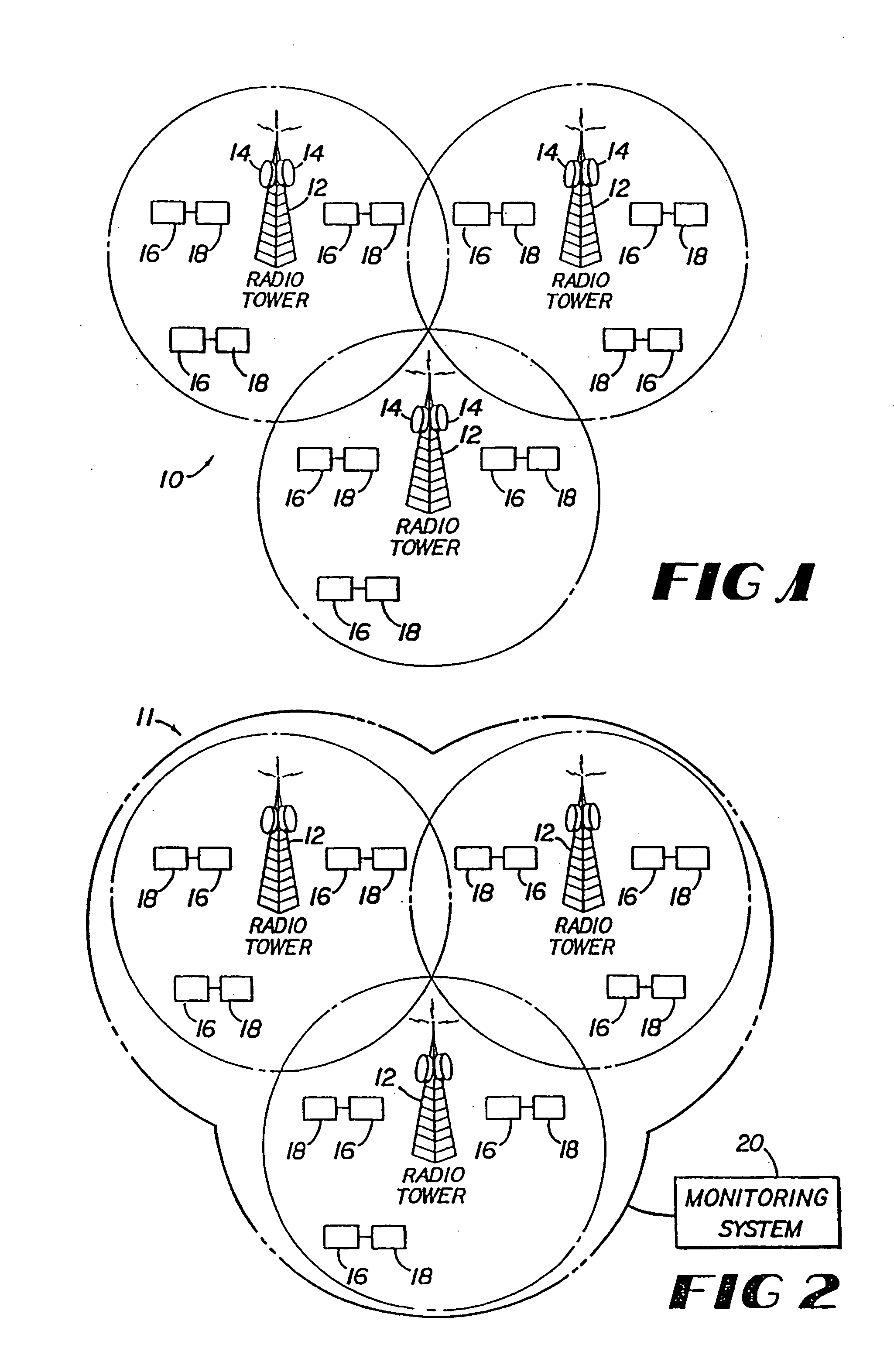
[0036]FIGS. 1-3 show monitoring and response systems 10, 11 and 13 respectively according to certain embodiments of the present invention. As shown in FIG. 1, monitoring and response system 10 includes a plurality of monitoring devices 14 adapted to detect or monitor at least one condition, a plurality of regional transmitters 12 communicatively associated with the monitoring devices 14, and a plurality of automatic response devices 16 adapted to receive signals from the regional transmitters12 and to perform certain functions. In other embodiments, such as the embodiments shown in FIGS. 2 and 3, a single monitoring device 20 replaces the plurality of monitoring devices 14 shown in FIG. 1. In still other embodiments, monitoring and response systems 10, 11 and / or 13 may include both types of monitoring devices 14 and 20.

[0037] Monitoring devices 14 and / or 20 may monitor any desired and / or appropriate condition, conditions, precursor condition or precursor conditions. For instance, m...


PUM


Abstract

A monitoring and response system including a monitoring device for detecting one or more conditions, a transmission system for sending control codes, and multiple devices for actively performing functions in response to the control codes. The monitoring device may consist of multiple detectors located in different geographic areas. The monitoring device may also be an external system. In the external monitoring device configuration, a centralized monitoring device detects and locates the conditions and transmits this information to the transmission system. The transmission system then transmits control commands to the devices.

Description

[0001] This application is a continuation-in-part of co-pending U.S. application Ser. No. 09 / 868,290 entitled “Lightning Protection Systems” filed Jun. 15, 2001, which is the national phase of International Application No. PCT / US00 / 00168 filed Jan. 5, 2000, which claims the benefit of U.S. Provisional Application No. 60 / 114,832 filed Jan. 6, 1999, all of which are herein incorporated in the entirety by this reference.RELATED FIELDS [0002] This invention relates to systems and devices for monitoring and automatically responding to detected conditions such as environmental conditions. BACKGROUND [0003] Environmental conditions can change suddenly, often with dramatic and potentially dangerous and / or harmful results. Lightning strikes can result in data loss and damage to electronic equipment. Excessive wind can damage windows. Large snowfalls can result in avalanches and roof collapses. Smog and other types of pollution can cause breathing problems. Clearly, environmental changes, whe...

Claims


Application Information

Patent Timeline
Patent Type & Authority Applications(United States)
IPC IPC(8): G01W1/16H01H3/26H02H3/22H02H5/00
CPCG01W1/16H02H5/005H02H3/22H01H3/26
Inventor PAGE, J. DENNIS
Owner STORM SHELTER
Why Eureka
Try Eureka