Centrifugal Fan, Cooling Mechanism, and Apparatus Furnished with the Cooling Mechanism

a centrifugal fan and cooling mechanism technology, applied in the direction of wind motors with parallel air flow, wind motors with perpendicular air flow, liquid fuel engine components, etc., can solve the problems of low peripheral speed of the impeller, slight noise from the airflow making a grating sound, etc., to secure the necessary airflow volume, increase the cooling power, and increase the static pressure

Inactive Publication Date: 2005-02-24
NIDEC CORP
View PDF11 Cites 25 Cited by
  • Summary
  • Abstract
  • Description
  • Claims
  • Application Information

AI Technical Summary

Benefits of technology

[0010] Objects of the present invention are: to realize an electronic-device cooling fan that is miniature, has large static pressure, and can secure the necessary airflow volume; and to realize a cooling device in which the fan is installed and that while being miniature has enhanced cooling power. In particular, an object of the invention lies in realizing a centrifugal fan as well as a cooling device that can be installed notebook personal computers, and moreover in devices such as compact PDAs and portable telephones also.

Problems solved by technology

What is more, while on the one hand the air-delivery capacity of the centrifugal fan is high, noise from the airflow making a grating sound is slight, because the peripheral speed of the impeller is low.

Method used


Image

  • Centrifugal Fan, Cooling Mechanism, and Apparatus Furnished with the Cooling Mechanism
  • Centrifugal Fan, Cooling Mechanism, and Apparatus Furnished with the Cooling Mechanism
  • Centrifugal Fan, Cooling Mechanism, and Apparatus Furnished with the Cooling Mechanism

Examples


embodiment 1

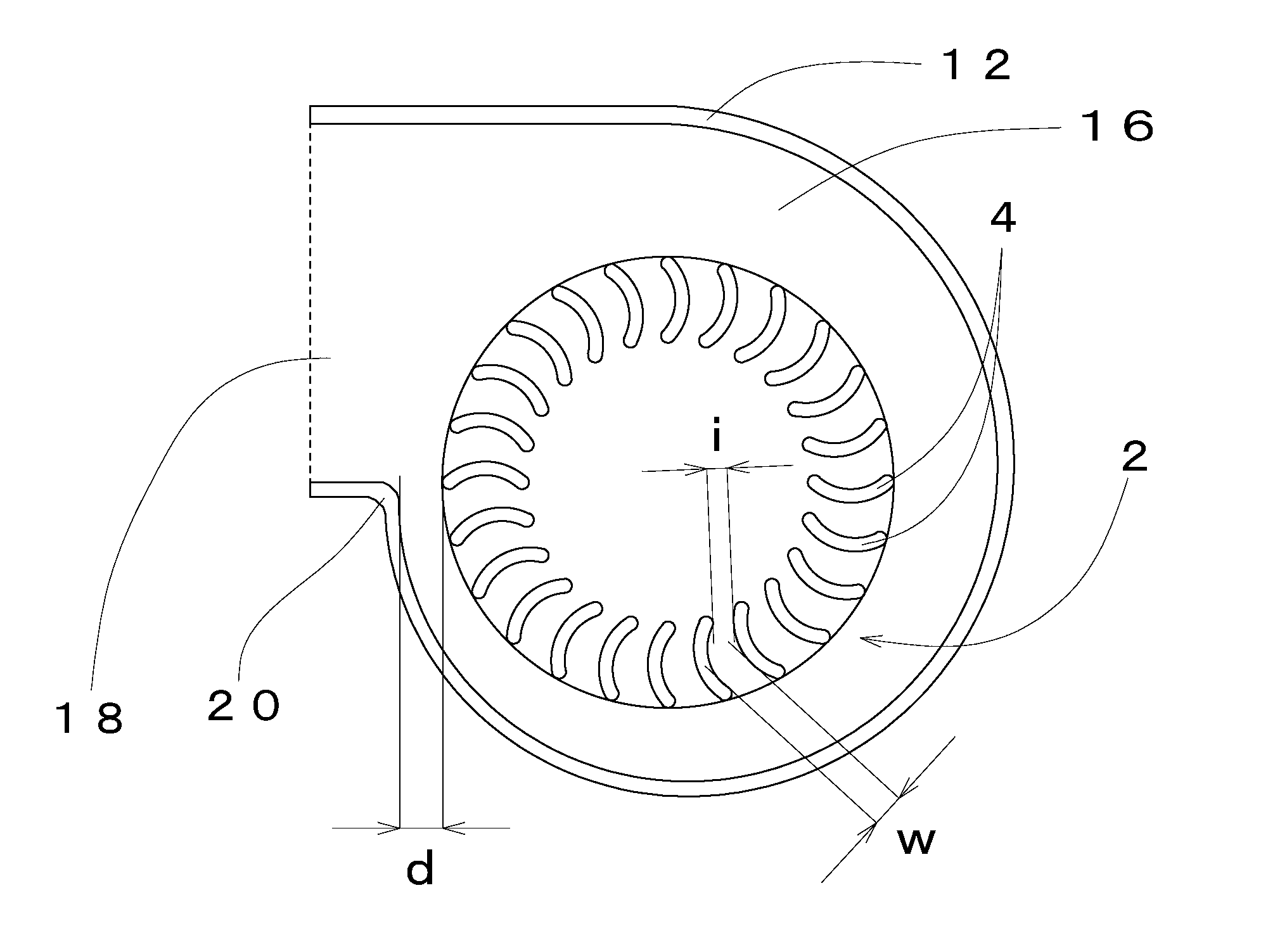
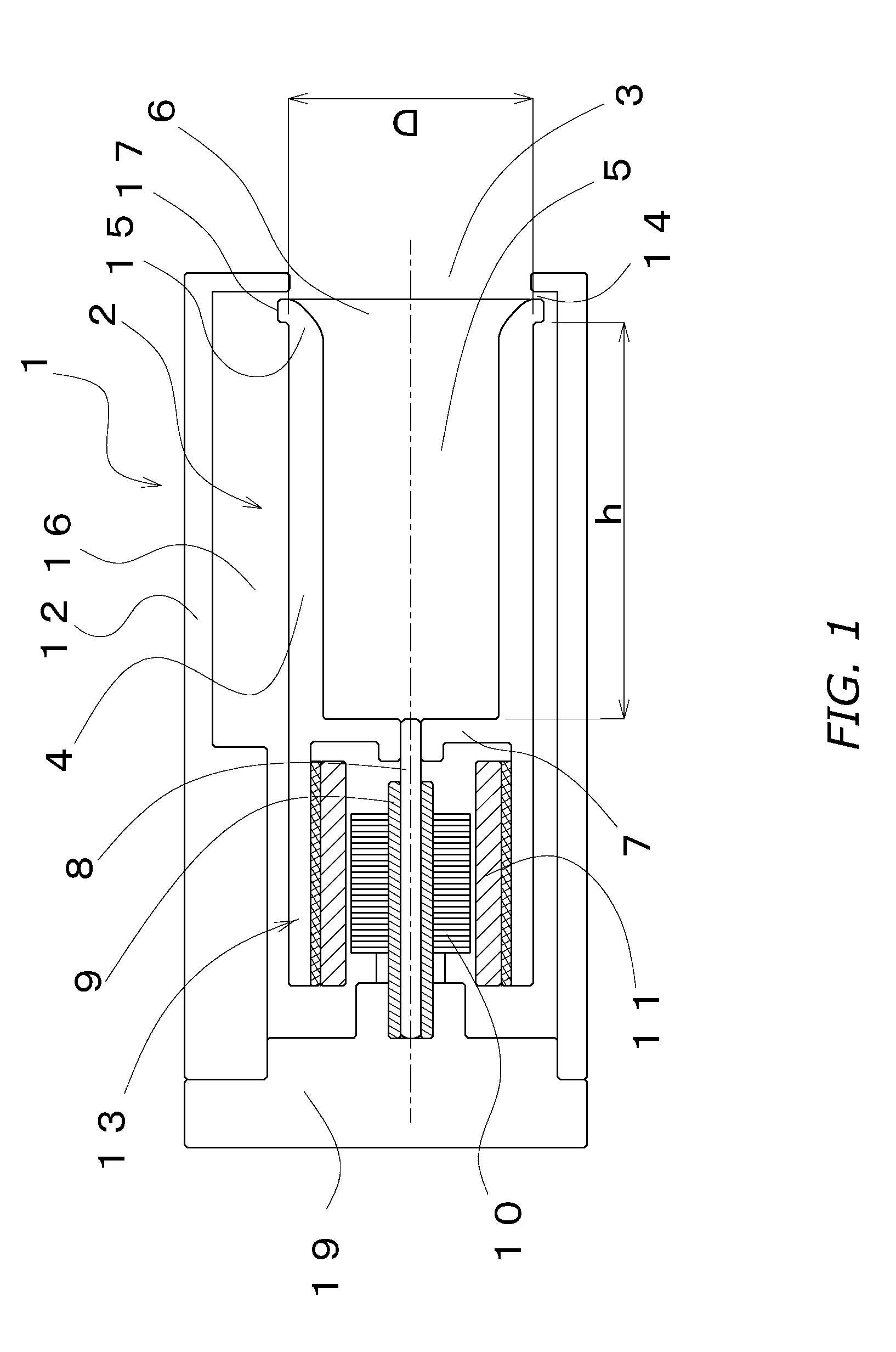
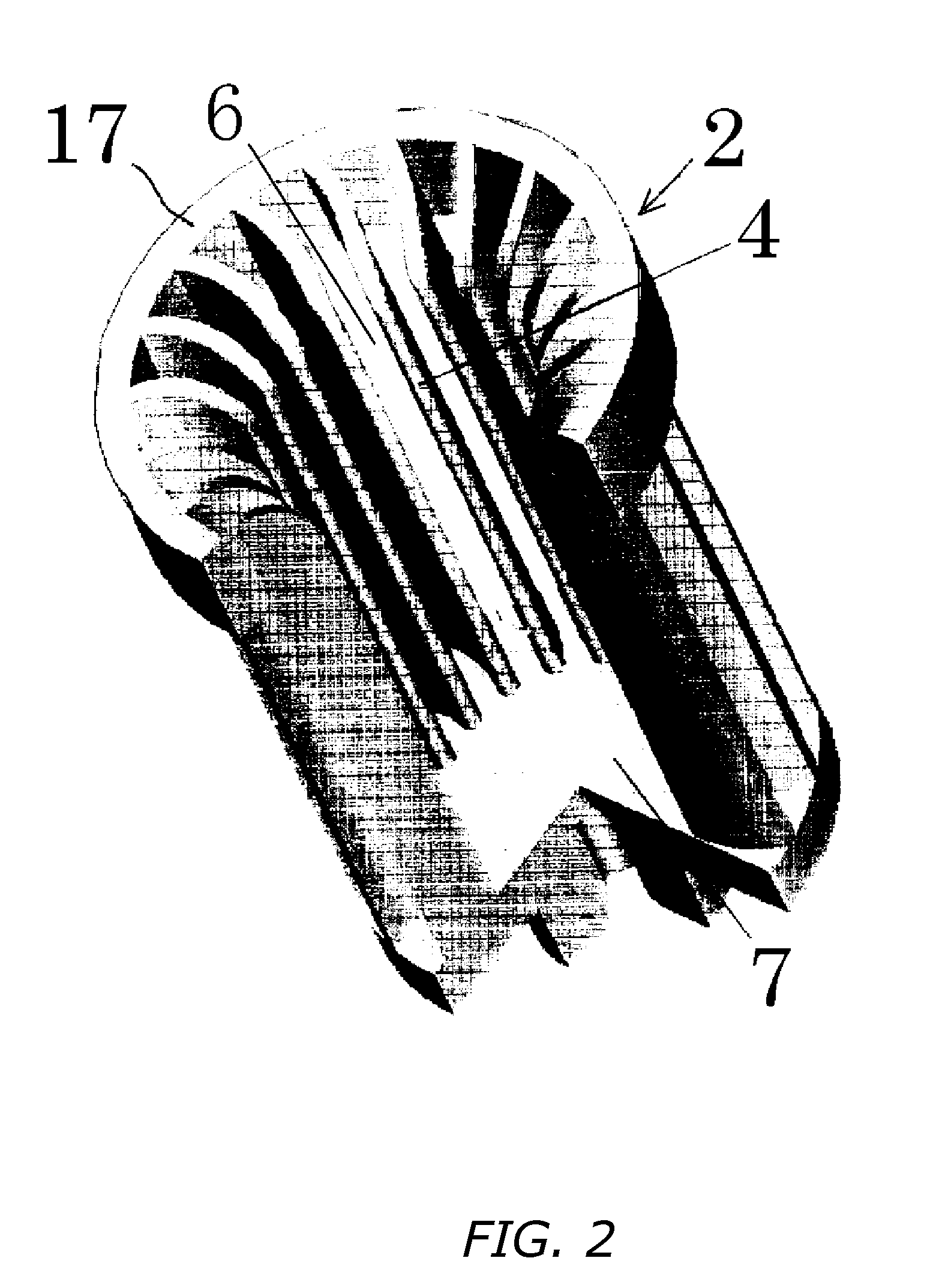
[0073] (1)Configuraton—Using FIGS. 1 through 3, an explanation of a centrifugal fan involving a first mode of embodying the present invention will be made. FIG. 1 illustrates a section through the centrifugal fan 1 in a plane in which the fan rotational axis lies. The centrifugal fan 1 is made up of an impeller 2, an outer-rotor motor 13 that rotationally drives the impeller 2, and a housing 12 that houses the impeller 2 and the motor 13. In the figure, “D” indicates the outer diameter of the impeller 2, which in this example is 6.75 mm. The impeller 2 has a plurality of vanes 4 that extend along the rotational axis, wherein the region encompassed by the vanes 4 forms a cavity 5. The cavity 5 along one end forms an opening 6, while the other end is closed off by a disk-shaped wall 7. Furthermore, the inner-circumferential edge of the fore ends of the vanes 4 along the opening 6 are worked into a bevel 15 so that the flow of sucked-in air is not disturbed.

[0074] The impeller 2 is fi...

embodiment 2

[0085] (1) Configuraton—A centrifugal fan involving a second embodiment of the present invention will be explained using FIGS. 5 through 8. FIG. 5 is a diagram of a centrifugal fan 101 in section along its rotational axis. In this centrifugal fan, differing from the fan detailed in Embodiment 1, two impeller components, 102a and 102b, connected by a shaft 108 configure a single impeller unit 102. Present in the ends of the impeller unit 102 are respective openings 106a and 106b.

[0086] A single motor component 113, an outer-rotor type, alone drives the impeller unit 102, and is formed unitarily with the impeller component 102a on one side of the fan. The impeller unit 102 and the motor component 113 together are housed inside a housing 112, wherein via a base 119 the motor component 113 is connected to and supported by the housing 112. While the draft cavity 116 in which the impeller unit 102 is accommodated does end up being partitioned in two by the base 119, a plurality of commun...

embodiment 3

[0105] (1) Circuit Board Furnished with a Cooling Mechanism—Reference is made now to FIG. 12, which illustrates a circuit board 301 furnished with a cooling mechanism involving the present invention. A CPU 302, which generates heat, is installed on the circuit board 301 on its top side. The centrifugal fan 1 involving the present invention is set in place onto the board 301 in order to cool the CPU 302. The fan 1 is anchored with the delivery port 18 directed at the CPU 302, which is therein directly cooled by the stream of air blown on it from the delivery port 18. A heatsink may be mounted directly onto the CPU 302, on its top side. It is to be noted that in FIG. 12 the structure that anchors the centrifugal fan 1 onto the circuit board 301 has been omitted.


PUM


Abstract

In a centrifugal fan the diameter of the impeller is rendered less than 20 mm, yet by rotating it under rotational conditions in which the centrifugal force along the impeller periphery is 10,000 m / s2 or more, the static pressure that the fan generates is heightened. At the same time, rendering the vane spacing a predetermined width or less reduces noise. Configuring in this way produces a small-scale, high-static-pressure, low-noise fan for cooling electronic devices. Furthermore, by mounting the centrifugal fan on a heatsink having densely arranged heat-dissipating projections a small-scale, high-cooling-capacity, quiet cooling device is realized.

Description

BACKGROUND OF INVENTION [0001] 1. Technical Field [0002] The present invention relates to centrifugal fans suited to cooling miniature devices that give off heat, and to heatsinks that with the centrifugal fan being mounted on them demonstrate excellent performance. In particular the present invention relates to centrifugal fans suited to being built into portable electronic devices, and to heatsinks furnished with the centrifugal fans. [0003] 2. Background Art [0004] With upgrading in the performance of electronic devices such as personal computers proceeding rapidly in recent years, there has been a trend toward an increase in the amount of heat issuing from devices such as CPUs, peripheral integrated circuits, hard disks, and power-supply circuits. In addition, as devices are being slimmed down and miniaturized further, the necessity for cooling mechanisms demonstrating sufficient cooling power within narrow confines has arisen. Such trends have been especially pronounced in so-c...

Claims


Application Information

Patent Timeline
Patent Type & Authority Applications(United States)
IPC IPC(8): F04D25/08F04D29/28F04D29/58
CPCF04D29/283F04D29/582F04D25/08H01L2924/0002Y10S416/02H01L2924/00
Inventor TAMAGAWA, TORUYOSHIDA, YUSUKE
Owner NIDEC CORP
Why Eureka
Try Eureka