Sensor system for sensing the mass concentration of particles in air

a sensor system and air mass technology, applied in the direction of suspensions and porous materials analysis, instruments, material analysis, etc., can solve the problems of sensor system complexity, inconvenient use, and inability to meet the needs of use, and achieve the effect of preventing contamination of sensor components

Active Publication Date: 2019-10-31
PRODRIVE TECH INNOVATION SERVICES BV
View PDF0 Cites 1 Cited by
  • Summary
  • Abstract
  • Description
  • Claims
  • Application Information

AI Technical Summary

Benefits of technology

[0010]A sensor system comprising a second flow fan for drawing the major flow through the first duct has the benefit that all flow rates (i.e. total flow, minor flow and major flow) can be adjusted, which enables an optimization of the separation efficiency for a much broader range of particle sizes. For example, 1) the total flow can be increased while keeping the ratio between the major flow and minor flow constant (see S0→S1 in FIG. 6), resulting in a sharper cut-off and a decrease in particle size threshold, or 2) the total flow can be kept constant while decreasing the flowrate in the major flow and thus increasing the flow rate in the minor flow (see S0→S2 in FIG. 6), resulting in a decrease in particle size threshold and a drop of the separation efficiency in the first duct for particles smaller than this threshold. It may be apparent from these examples that a large variety of flow rates can be achieved so filter performance may be enhanced for various particle size thresholds.
[0023]The clean air of the sheath flow is for instance generated by filtering the particles contained in the part of the major flow that is provided to the filter. The velocity of the sheath flow is lower than the sample flow (e.g. 3× to 7× lower, preferably about 5x lower) such that the dynamic pressure of the sample flow increases at the expense of the static pressure of the sample flow. This results in a static pressure of the sheath flow that is larger than the static pressure of the sample flow. The pressure gradient aims to avoid the particles that are present in the sample flow to diverge out of the sample flow and thereby prevents contamination of the sensor components during operation of the system according to the present disclosure.

Problems solved by technology

Most of the known systems are not suitable to be used in applications where conditions (e.g. vibration, temperature, humidity, pressure) are variable and other constraints (e.g. size, weight, noise) are applicable, like the sampling of air from various sources in and around a moving vehicle (e.g. environmental air, air from the HVAC system or cabin air).
Therefore, such a sensor system is more complex than is required if only the aggregated mass concentration of particles smaller than a certain threshold is of interest.
Consequently it is typically more costly, fragile, heavier and larger than is required and suitable in various situations (e.g. in a vehicle).
Furthermore, this sensor system uses pumps or blowers capable of generating a high pressure gradient to generate a constant flow, which are typically more bulky, noisier and consume more power than is acceptable in some circumstances.
However, a disadvantage of the described sensor system is that it is optimized for a continuous real-time measurement of particles that are smaller than a single (or a small range of) threshold(s), because the geometry of the virtual impactor is fixed and varying the total flow will consequently not only change the particle size threshold but also alter the separating efficiency.
Furthermore, it reduces the exposure of components of the sensor system like the sensor to polluting particles in the major flow that may limit their life time.
In addition, it requires a smaller pressure gradient and thereby consumes less power and enables the use of fans instead of pumps or blower that are more costly, more voluminous and noisier.
This results in a static pressure of the sheath flow that is larger than the static pressure of the sample flow.

Method used


Image

  • Sensor system for sensing the mass concentration of particles in air
  • Sensor system for sensing the mass concentration of particles in air
  • Sensor system for sensing the mass concentration of particles in air

Examples


Embodiment Construction

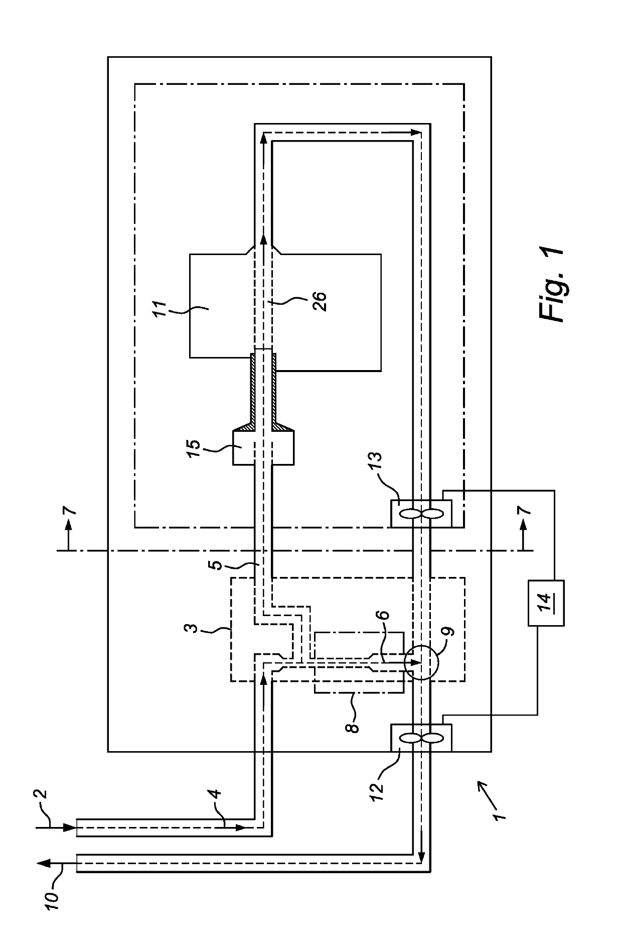
[0034]FIG. 1 shows a schematic overview of a system 1 according to the present invention. The system 1 comprises an inlet 2 for receiving a total flow 4 of air with particles, which inlet 2 is connected to a first splitter 3 for separating the total flow of air into a major flow 5 and a minor flow 6, wherein the major flow 5 comprising particles smaller than the predetermined threshold and the minor flow 6 comprising particles larger than the predetermined threshold and for leading the major flow to a first duct 7 and for leading the minor flow 6 to a second duct 8. Both ducts 7, 8 come together at a joint 9, which is coupled to an outlet 10. The system 1 also comprises a sensor 11, arranged in the first duct 7 for measuring the amount of particles smaller than the predetermined threshold comprised in the major flow 5 and a first flow fan 12 for drawing the total flow 4 through the system 1. The system 1 further comprises a second flow fan 13 for drawing the major flow through the f...


PUM

PropertyMeasurementUnit
aerodynamic diameteraaaaaaaaaa
pressureaaaaaaaaaa

Abstract

The present application relates to sensor systems for sensing mass concentration of particles smaller than a predetermined threshold in an air stream. Such systems may include an inlet (for receiving a total flow of air with particles) connected to a first splitter (for separating the total flow into a major flow and a minor flow), a joint where a first duct carrying the major flow and a second duct carrying the minor flow come together, and a sensor in the first duct for measuring the amount of particles smaller than the predetermined threshold in the major flow.

Description

FIELD[0001]The present disclosure relates to a sensor system for sensing the mass concentration of particles in air, a sensor unit and a method for operating said sensor unit. The present disclosure further relates to a vehicle comprising a sensor system and a sensor unit.INTRODUCTION[0002]Fine particulate matter has been receiving increasing attention during the past decades due to the increased emissions of these particles and their adverse effects on air quality with respect to health. These particles typically have an aerodynamic diameter smaller than 10 μm (i.e. PM10), wherein the smaller particles (e.g. smaller than or equal to 2.5 μm or PM2.5, smaller than or equal to 1.0 μm or PM1.0 and smaller than or equal to 0.1 μm or PM0.1) appear to have the most adverse effect on air quality. In traffic in general and specifically in traffic jams, in tunnels or at a traffic light the effect on air quality may even be further aggravated because of the increased local particle concentrat...

Claims


Application Information

Patent Timeline
Patent Type & Authority Applications(United States)
IPC IPC(8): G01N15/14G01N15/02
CPCG01N15/0205G01N15/0255G01N15/1459G01N2015/025G01N1/2202G01N1/2208G01N15/06G01N2015/0693G01N1/2247
Inventor VAN DEN HOOGEN, DJAREK HENDRIKUS JOSEPHUS MARIASTAPS, TIMMY JACOBUS ADRIANUSSZYMCZYK, KRZYSZTOF STANISLAW
Owner PRODRIVE TECH INNOVATION SERVICES BV
Why Eureka
Try Eureka