Driving system for fan and method of driving fan

a technology of driving system and fan, which is applied in the direction of mechanical energy handling, mechanical equipment, machines/engines, etc., can solve the problems of excessive rotational speed and excessive consumption of power, and achieve the effect of preventing rotational speed (motor current)

Active Publication Date: 2011-12-08
SANYO DENKI CO LTD
View PDF6 Cites 4 Cited by
  • Summary
  • Abstract
  • Description
  • Claims
  • Application Information

AI Technical Summary

Benefits of technology

[0012]The present invention also provides a method of driving a fan that includes an impeller and a motor rotating the impeller, and that produces a maximum static pressure when the motor rotates the impeller at a maximum speed and that produces a maximum amount of air flow when the motor rotates the impeller at a minimum speed. The method according to the present invention includes the step of restricting an increase in a motor current supplied to the motor such that a value of the motor current does not become larger than a predetermined threshold. Here, the phrase “a value of the motor current does not become larger than a predetermined threshold” means to perform current restricting control such that the value of the motor current does not continuously exceed the threshold, rather than such that the value of the motor current never exceeds the threshold. Thus, the motor current may exceed the threshold during the current restricting control. According to the method of the present invention, an increase in motor current is restricted such that the motor current does not become larger than the threshold. Therefore, it is possible to prevent the rotational speed (motor current) at the time of a maximum amount of air flow from becoming excessive even if the specifications of the excitation windings are determined to increase the motor current that may be supplied to the excitation windings at the time of a maximum static pressure. Viewed from another aspect, the specifications of the excitation windings and the threshold may be set to increase the maximum static pressure without changing the maximum amount of air flow.
[0013]The method of the present invention also allows changing the maximum amount of air flow by changing the threshold.

Problems solved by technology

If the excitation windings W with specifications required to obtain a rotational speed required for the maximum static pressure MP are used with the conventional driving system shown in FIG. 6, however, the rotational speed may become excessive at the time of the maximum amount of air flow MQ to consume excessive power.

Method used


Image

  • Driving system for fan and method of driving fan
  • Driving system for fan and method of driving fan
  • Driving system for fan and method of driving fan

Examples


Embodiment Construction

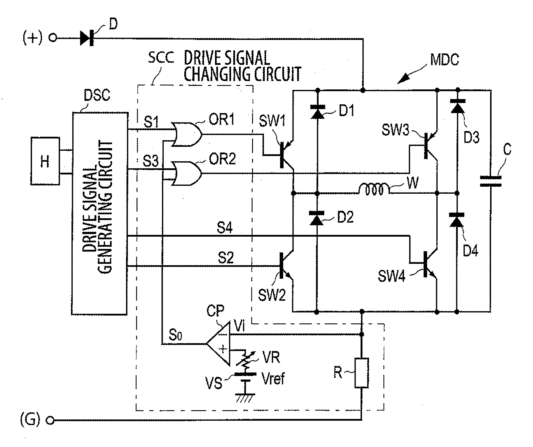
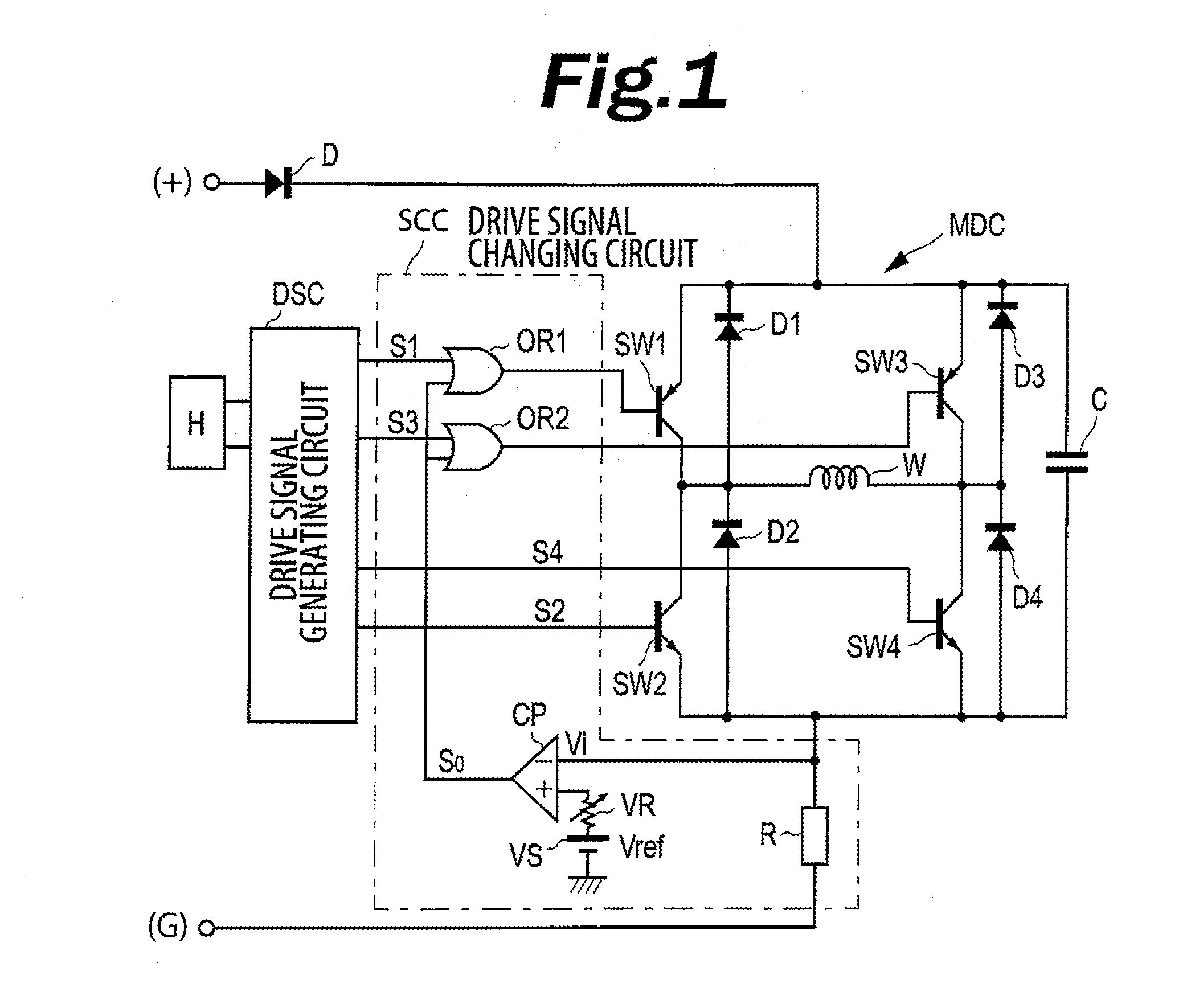
[0023]A driving system for a fan and a method of driving a fan according to an embodiment of the present invention will be described in detail below with reference to the drawings. FIG. 1 shows the circuit of a driving system for a centrifugal fan according to an embodiment of the present invention. Components that are the same as those of the circuit according to the conventional driving system shown in FIG. 6 are denoted by reference numerals that are the same as those given in FIG. 6.

[0024]In the embodiment of FIG. 1, a drive signal generating circuit DSC generates drive signals S1 to S4 with a predetermined cycle. A motor driving circuit MDC comprises a bridge circuit including transistors (semiconductor switches) SW1 to SW4, regenerative diodes D1 to D4, and a snubber capacitor C. The drive signal generating circuit DSC detects the rotor position on the basis of an output from a magnetic sensor H of a Hall element that detects magnetism of a plurality of permanent magnets provi...


PUM


Abstract

A driving system for a fan that enables an increase in motor current that may be supplied to excitation windings at the time of a maximum static pressure without increasing the rotational speed excessively when an amount of maximum air flow is provided. The fan driving system includes a drive signal generating circuit that generates drive signals, a motor driving circuit that supplies a motor current to the motor in accordance with the drive signals, a current detecting circuit (resistance) that detects the motor current, and a drive signal changing circuit. The drive signal changing circuit changes the drive signals generated by the drive signal generating circuit to restrict an increase in the motor current when the motor current becomes larger than a threshold.

Description

BACKGROUND OF THE INVENTION[0001]1. Field of the Invention[0002]The present invention relates to a driving system for a fan with a higher maximum static pressure and a method of driving the fan.[0003]2. Description of the Related Art[0004]Japanese Unexamined Patent Application Publication No. 2002-61596 discloses the structure of a centrifugal fan as an example of a fan that includes an impeller and a motor rotating the impeller, and that produces a maximum static pressure when the motor rotates the impeller at a maximum speed and that produces a maximum amount of air flow when the motor rotates the impeller at a minimum speed. Japanese Unexamined Patent Application Publication No. 2002-112570 discloses a driving system for a brushless fan motor including a centrifugal fan and a method of driving the brushless fan motor. FIG. 6 shows an example of the circuit of a conventional driving system for a centrifugal fan. The conventional driving system includes a drive signal generating ci...

Claims


Application Information

Patent Timeline
Patent Type & Authority Applications(United States)
IPC IPC(8): F04D15/00H02P6/06H02P6/08H02P6/26H02P6/28
CPCF04D27/004Y02B30/70F04D25/08F04D27/00F05D2210/12F05D2270/30H02P29/10
Inventor MITOMO, SHIGEKAZUYEN, KEVIN
Owner SANYO DENKI CO LTD
Why Eureka
Try Eureka