Centrifugal fan, cooling mechanism, and apparatus furnished with the cooling mechanism
a centrifugal fan and cooling mechanism technology, applied in the direction of wind motors with parallel air flow, wind motors with perpendicular air flow, liquid fuel engine components, etc., can solve the problems of low peripheral speed of the impeller, slight noise from the airflow making a grating sound, etc., to secure the necessary airflow volume, increase the cooling power, and increase the static pressure
- Summary
- Abstract
- Description
- Claims
- Application Information
AI Technical Summary
Benefits of technology
Problems solved by technology
Method used
Image
Examples
embodiment 1
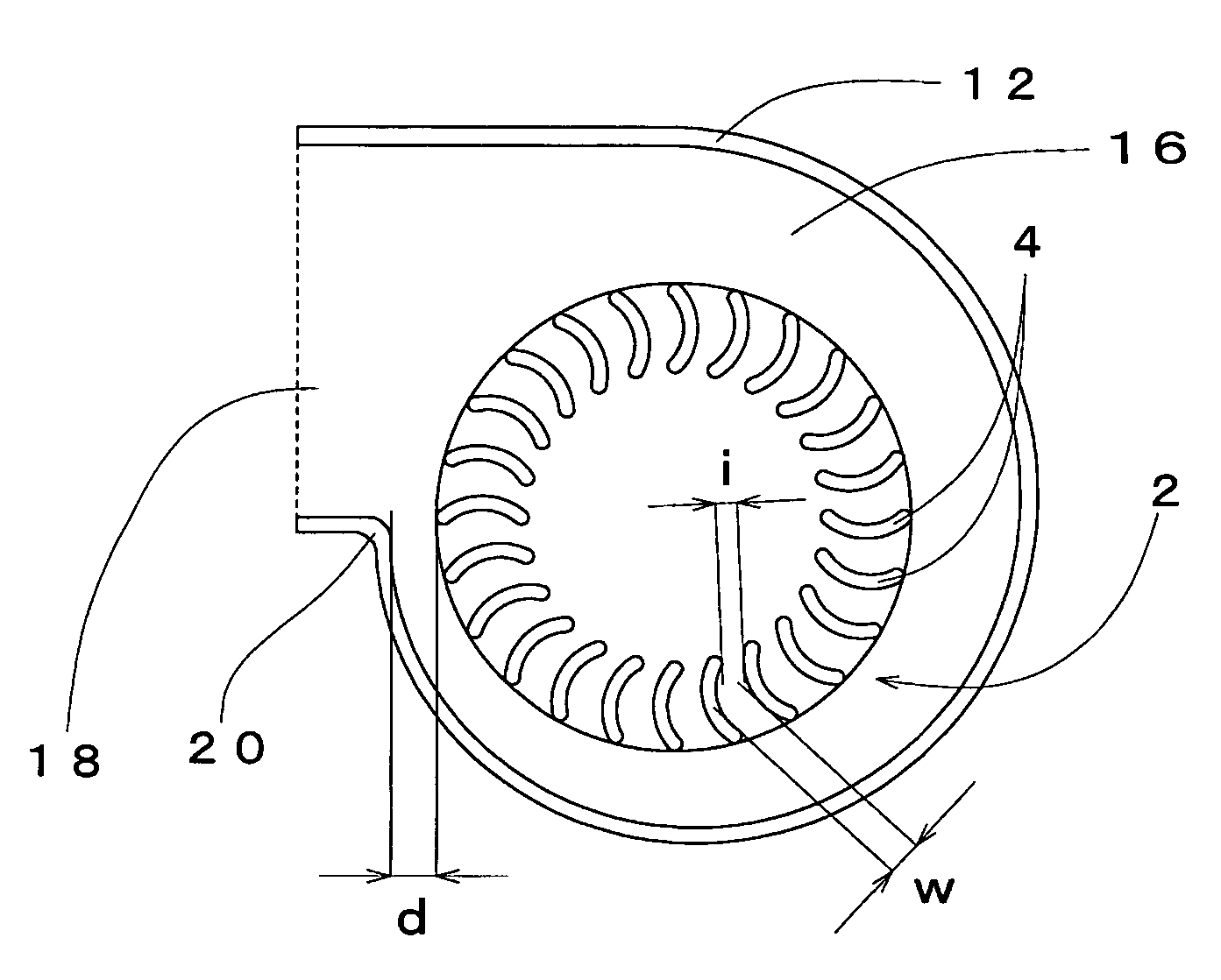
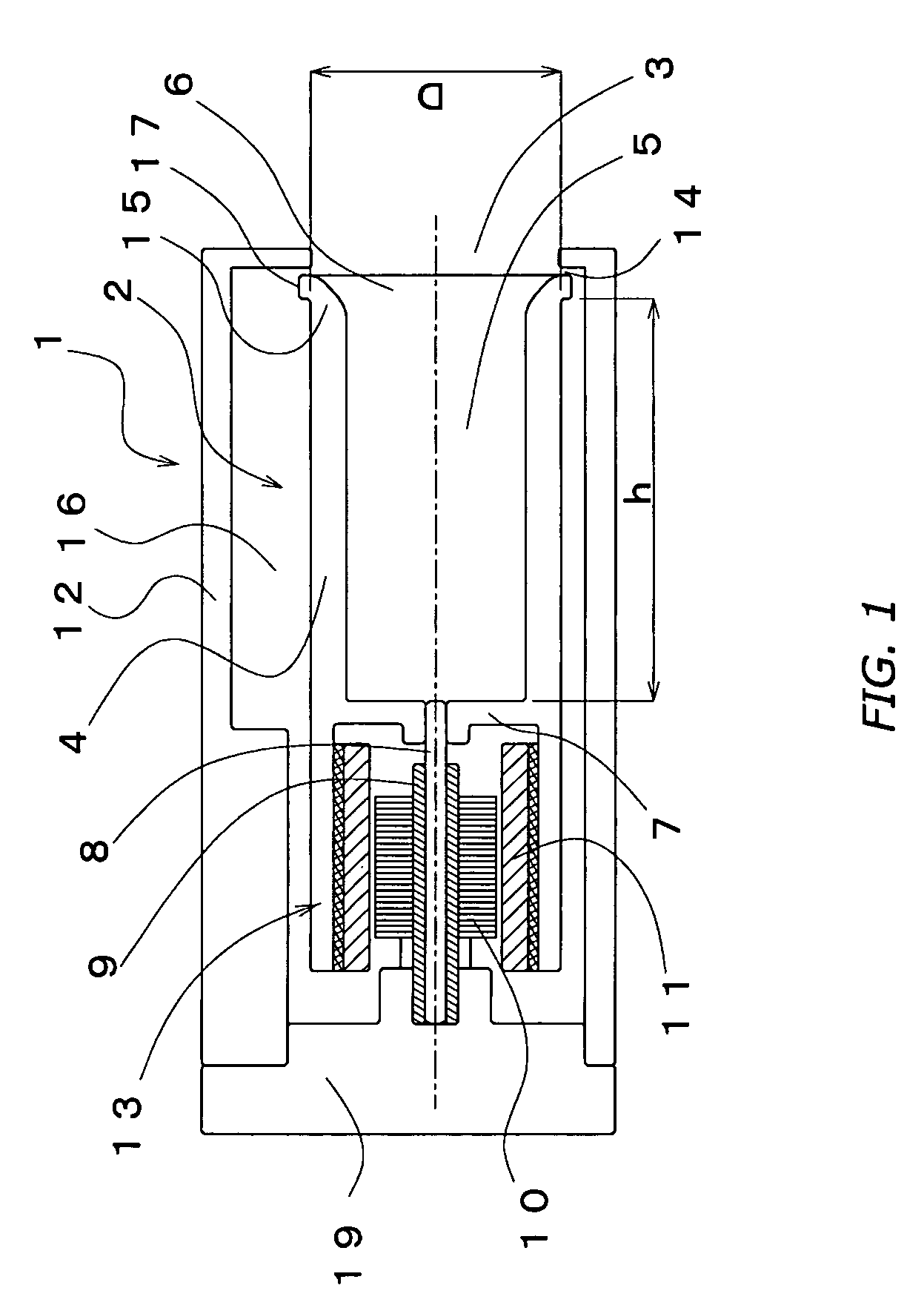
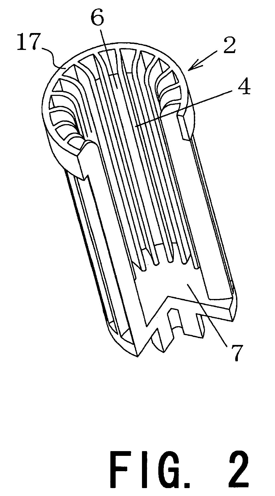
[0073](1) Configuraton—Using FIGS. 1 through 3, an explanation of a centrifugal fan involving a first mode of embodying the present invention will be made. FIG. 1 illustrates a section through the centrifugal fan 1 in a plane in which the fan rotational axis lies. The centrifugal fan 1 is made up of an impeller 2, an outer-rotor motor 13 that rotationally drives the impeller 2, and a housing 12 that houses the impeller 2 and the motor 13. In the figure, “D” indicates the outer diameter of the impeller 2, which in this example is 6.75 mm. The impeller 2 has a plurality of vanes 4 that extend along the rotational axis, wherein the region encompassed by the vanes 4 forms a cavity 5. As an embodiment, the cavity is approximately circular-cylindrical as illustrated in FIGS. 1 and 2. The cavity 5 along one end forms an opening 6, while the other end is closed off by a disk-shaped wall 7. Furthermore, the inner-circumferential edge of the fore ends of the vanes 4 along the opening 6 are wo...
embodiment 2
[0085](1) Configuraton—A centrifugal fan involving a second embodiment of the present invention will be explained using FIGS. 5 through 8. FIG. 5 is a diagram of a centrifugal fan 101 in section along its rotational axis. In this centrifugal fan, differing from the fan detailed in Embodiment 1, two impeller components, 102a and 102b, connected by a shaft 108 configure a single impeller unit 102. Present in the ends of the impeller unit 102 are respective openings 106a and 106b.
[0086]A single motor component 113, an outer-rotor type, alone drives the impeller unit 102, and is formed unitarily with the impeller component 102a on one side of the fan. The impeller unit 102 and the motor component 113 together are housed inside a housing 112, wherein via a base 119 the motor component 113 is connected to and supported by the housing 112. While the draft cavity 116 in which the impeller unit 102 is accommodated does end up being partitioned in two by the base 119, a plurality of communic...
embodiment 3
[0105](1) Circuit Board Furnished with a Cooling Mechanism—Reference is made now to FIG. 12, which illustrates a circuit board 301 furnished with a cooling mechanism involving the present invention. A CPU 302, which generates heat, is installed on the circuit board 301 on its top side. The centrifugal fan 1 involving the present invention is set in place onto the board 301 in order to cool the CPU 302. The fan 1 is anchored with the delivery port 18 directed at the CPU 302, which is therein directly cooled by the stream of air blown on it from the delivery port 18. A heatsink may be mounted directly onto the CPU 302, on its top side. It is to be noted that in FIG. 12 the structure that anchors the centrifugal fan 1 onto the circuit board 301 has been omitted. As an embodiment, the present invention provides a method for cooling a heat-emitting component, CPU 302, mounted on a circuit board 301. The heat-emitting component cooling method includes the steps of the following: fixing a ...
PUM
 Abstract
Description
Claims
Application Information
 - R&D
- Intellectual Property
- Life Sciences
- Materials
- Tech Scout
- Unparalleled Data Quality
- Higher Quality Content
- 60% Fewer Hallucinations
Browse by: Latest US Patents, China's latest patents, Technical Efficacy Thesaurus, Application Domain, Technology Topic, Popular Technical Reports.
© 2025 PatSnap. All rights reserved.Legal|Privacy policy|Modern Slavery Act Transparency Statement|Sitemap|About US| Contact US: help@patsnap.com


