
Multi-functional measuring and layout device

a layout device and multi-functional technology, applied in the field of measuring devices, can solve the problems of not offering the multitude of uses and teaching aids of these devices, and achieve the effect of low cos

Inactive Publication Date: 2005-03-03
BLOUCH RUTH G
View PDF28 Cites 4 Cited by
  • Summary
  • Abstract
  • Description
  • Claims
  • Application Information

AI Technical Summary

Benefits of technology

[0019] This patent addresses a device that reinforces teaching and understanding of units of measure by incorporating various tactile as well as visual qualities of said units of measure to enhance their representation and application to spatial relationships resulting in better acquisition of resultant quantities by the device user. It is suitable for widespread use among sighted and non-sighted students and the general populace.
[0046] Wrapping cordage about the measuring device allows the transference and replication of the measuring device features upon the cord. Such an auxiliary cord also can be stored conveniently in a compartment within the measuring device or stowed while remaining attached, in its own package compatible with the user's handling of the measuring device.

Problems solved by technology

Limitations of this patent are; the device only teaches fractional units of measure, cannot respond to distances not allowing lengthwise registration of the device, cannot accomplish center locating or bifurcating functions, and for the flexible embodiment, the assisted reading (labeled graduations) are not direct reading (applied to the observed distance).
However, none of these offer the multitude of uses and teaching aids that the current invention provides.

Method used


Image

  • Multi-functional measuring and layout device
  • Multi-functional measuring and layout device
  • Multi-functional measuring and layout device

Examples


Embodiment Construction

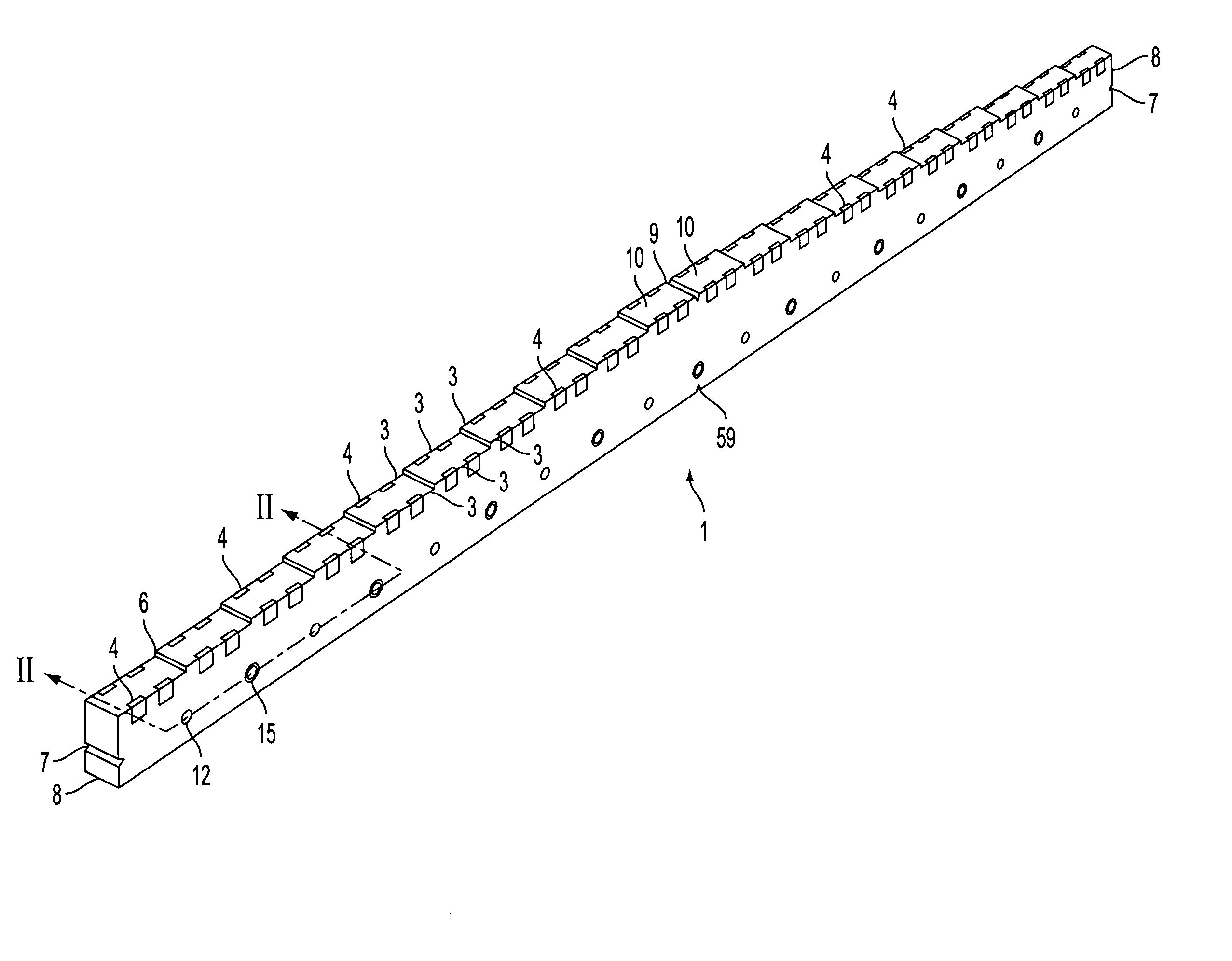
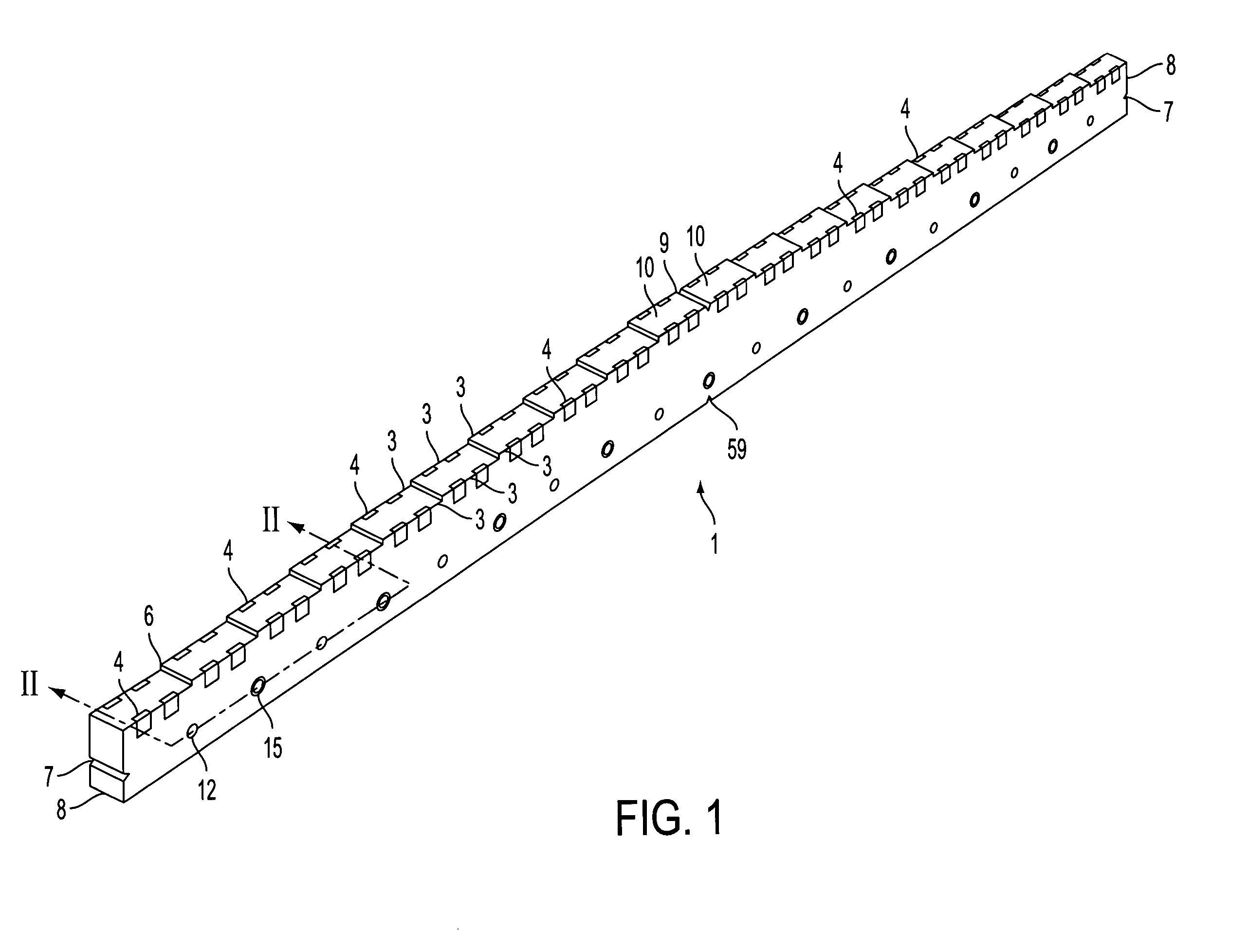
[0060] As will be described below, the measuring and layout device has multiple advantages including the ability to be constructed in a simple manner and produced economically. Moreover, it can be made from durable, impact resistant and flexible material. The measuring device has numerous uses as a linear measurement aid and a linear units educational tool. It is designed with a series of elevated steps as well as a series of depressed and elevated increments representative of two differing degrees of resolution. All graduations are both visually and tactually discernable, thus making the measuring device useful for the sight impaired as well as the general population. Deployed near the bottom edge of the device is an array of holes that can be used for geometric and trigonometric measurements and layouts. The V-shaped notches on the top and bottom edges at a mesial location aid use of the device as a center finder, scribe, or balance. The V-shaped notches on the proximal and distal...


PUM


Abstract

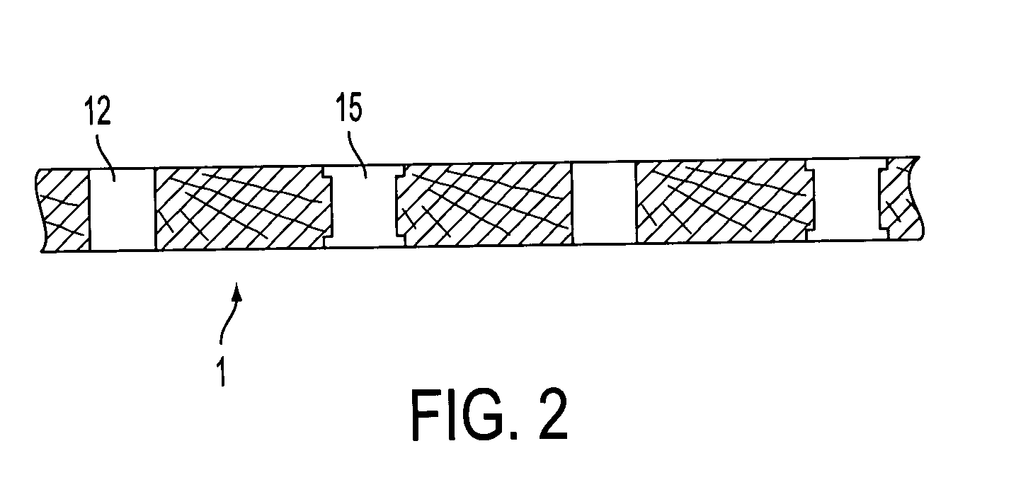
A multi-functional measuring device made of lightweight material planed on one edge in a succession of ascending and descending steps representing dimensional increments. Successive steps ascend over one-half the length of the device and, at the mid-point, level off and begin to descend in dimensional increments for the remaining length, providing a visual image and tactile profile for the user. Centerline notches are cut on both the upper and lower edges, and are used to locate the center point of an object. High and low profiles are cut into specific locations to allow for visual and tactile determination of specific subdivision dimensions. A notch is provided at each end of the device to accommodate linear measurements exceeding the length of the device. The lower face surface is punctuated with a series of holes. Small diameter holes, marking dimensional increments, are arranged in a straight line parallel to the lower edge, opposite the ascending and descending steps. Large diameter holes, marking additional dimensions, are arranged in an alternating pattern with the small diameter holes.

Description

CROSS-REFERENCE TO RELATED APPLICATIONS [0001] None STATEMENT REGARDING FEDERALLY SPONSORED RESEARCH OR DEVELOPMENT [0002] None REFERENCE TO SEQUENCE LISTING, A TABLE, OR A COMPUTER PROGRAM LISTING COMPACT DISK APPENDIX [0003] None BACKGROUND OF THE INVENTION [0004] 1. Field of the Invention [0005] The field of this invention is measuring devices. Vast multitudes of measuring devices have been created and used through the course of time to measure not only linear dimensions but also non-linear dimensions. Measuring devices allow the user to qualify spatial relationships observed in a two dimensional format. Systems of measurement are based on either the English system with the foot as the base unit of measure or the metric system with the meter as the base unit of measure. The English system is divided into fractional parts and the metric system is divided into decimal portions of the meter. [0006] The present invention relates to a measuring apparatus and methods for measuring and ...

Claims


Application Information

Patent Timeline
Patent Type & Authority Applications(United States)
IPC IPC(8): B25H7/00G01B3/30
CPCG01B3/30B25H7/00
Inventor BLOUCH, RUTH G.
Owner BLOUCH RUTH G
Learn More