
Combustor of a gas turbine engine

a gas turbine engine and combustor technology, applied in the direction of machines/engines, mechanical equipment, lighting and heating apparatus, etc., can solve the problems of carbon monoxide formation at the periphery of the combustor, and the inability to obtain the maximum cooling potential from the available mass of cooling air while still maintaining low emissions

Inactive Publication Date: 2005-03-03
SOLAR TURBINES
View PDF12 Cites 46 Cited by
  • Summary
  • Abstract
  • Description
  • Claims
  • Application Information

AI Technical Summary

Benefits of technology

The patent describes a new design for a combustor in a gas turbine engine. The design includes a first liner and a first convector, with a plurality of passages positioned between them. One of the passages has a length that is greater than the distance between the first liner and the first convector. The design also includes means for causing the fluid to move in a direction nonparallel to the central axis. The technical effect of this design is improved cooling of the combustor liner, which reduces the risk of damage from high temperatures.

Problems solved by technology

However, one problem shared by many different cooling schemes is an inability to obtain the maximum cooling potential from the available mass of cooling air while still maintaining low emissions.
For example, one potential problem with film cooling, a very effective cooling method, is the formation of carbon monoxide at the periphery of the combustor.

Method used


Image

  • Combustor of a gas turbine engine
  • Combustor of a gas turbine engine
  • Combustor of a gas turbine engine

Examples


Embodiment Construction

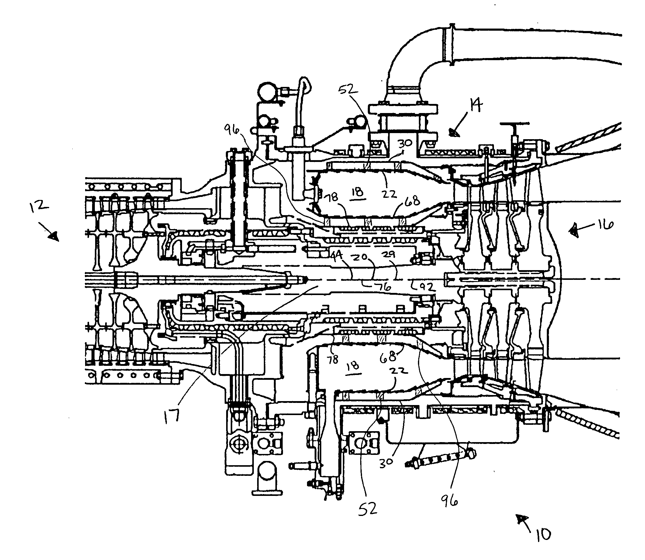
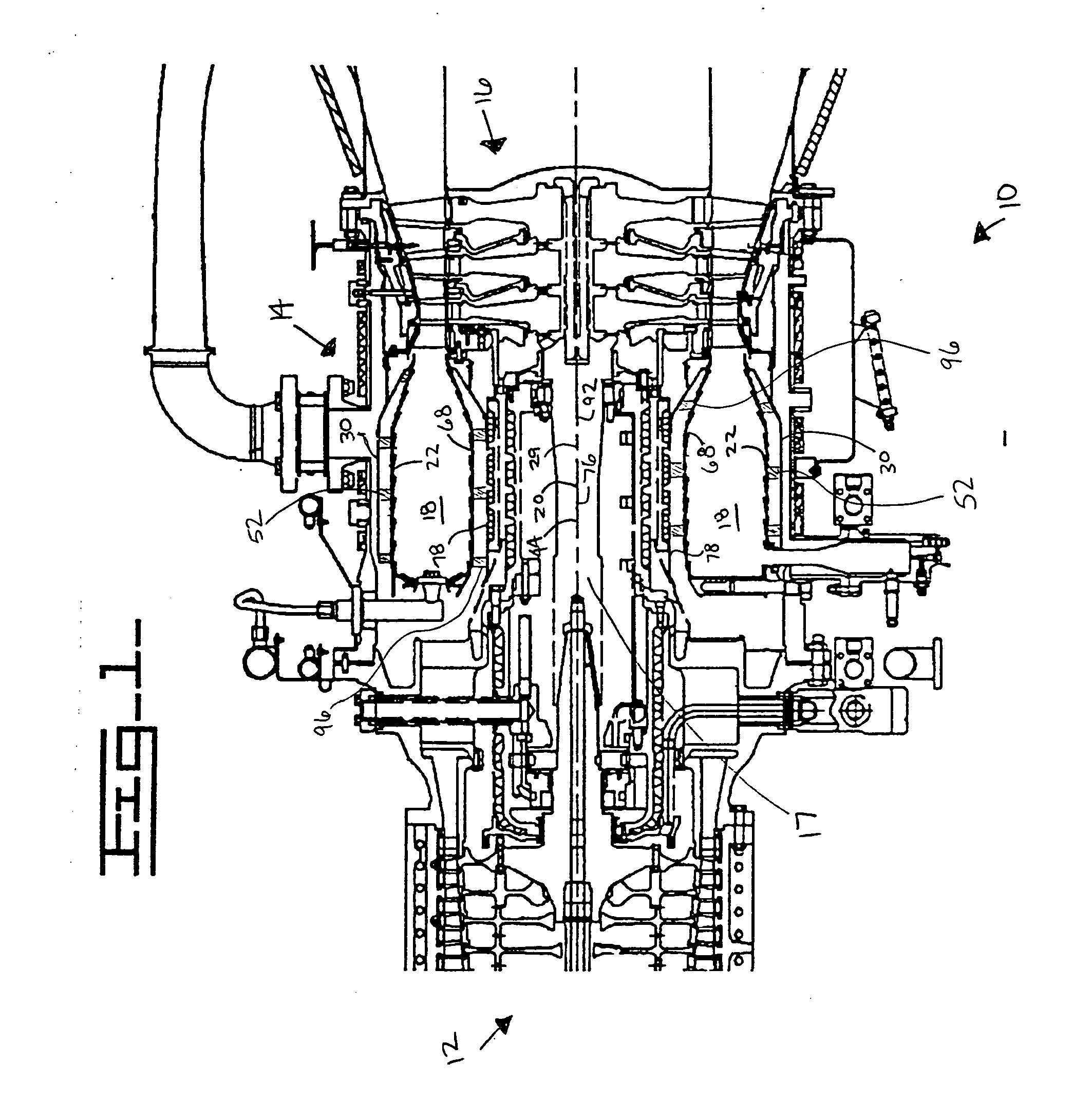
[0014] Referring to FIG. 1, an embodiment of a gas turbine engine 10 is shown having a compressor 12, a combustor 14, and a turbine 16. The combustor 14 is in fluid communication with the compressor 12, and the turbine 16 is in fluid communication with the combustor 14. The turbine 16 is connected to the compressor 12 via a force-transmitting device 17, such as a shaft or gear system. The combustor 14 defines a combustion zone 18 of the gas turbine engine 10. In the embodiment of FIG. 1, the combustor 14 of the gas turbine engine 10 is an annular combustor and has a central axis 20. However, in other embodiments, the combustor 14 may be tubular with a single can, tubular with multiple cans, tuboannular, or any other configuration known in the art. In the embodiment of FIG. 1, the combustor 14 is generally in the shape of a cylinder joined to a conical frustum. However, the combustor 14 may approximate any other shape or combination of shapes, such as a cylinder, an elliptic cylinder...


PUM


Abstract

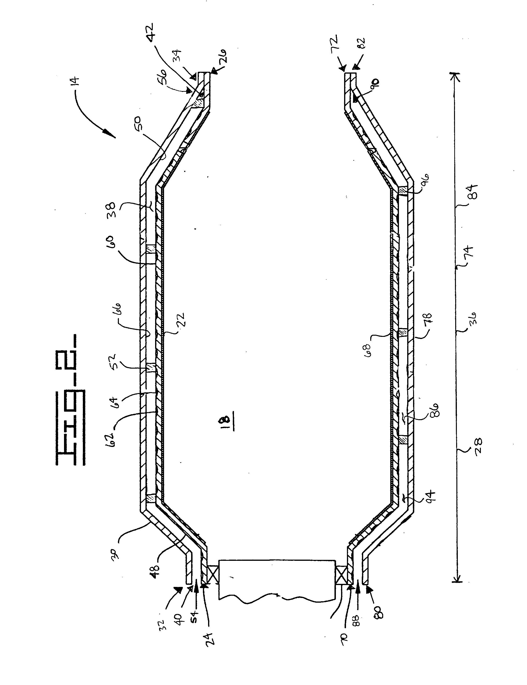
A combustor has a combustion zone and a liner bounding the combustion zone. The liner has a first end portion and a second end portion spaced a defined distance from the first end portion. The combustor has a convector spaced apart from the liner. The convector has a first end portion and a second end portion spaced a defined distance of the first end portion. A plurality of passages are located between the liner and the convector. One of the passages has a length that is longer than at least one of the defined distance of the liner and the defined distance of the convector.

Description

TECHNICAL FIELD [0001] This invention relates generally to a gas turbine engine and more specifically to cooling of a liner of a combustor of a gas turbine engine. BACKGROUND [0002] Current gas turbine engines continue to improve emissions and engine efficiencies. Notwithstanding these improvements, further increases in engine efficiencies will require more effective use of a mass of compressed air exiting a compressor. Gas turbine engines normally use the mass of compressed air for: 1) combustion air, 2) dilution air, 3) combustor cooling air, and 4) turbine component cooling air. Each use of the mass of compressed air may vary according to a load on the gas turbine engine. Generally each of these uses requires more of the mass of compressed air as the load increases. [0003] In particular, combustion air and combustor cooling air have increased in importance with increasing regulations of NOx (an uncertain mixture of oxides of nitrogen). The efficiencies of the gas turbine engine u...

Claims


Application Information

Patent Timeline
Patent Type & Authority Applications(United States)
IPC IPC(8): F23R3/00F23R3/42F23R3/44
CPCF23D2214/00F23R3/44F23R3/002
Inventor GLEZER, BORISMOON, HEE KOO
Owner SOLAR TURBINES
Learn More