Oil pressure control system and method for engines with hydraulic cylinder deactivation

a technology of oil pressure control system and hydraulic lifter, which is applied in the direction of valve arrangement, pressure lubrication, machines/engines, etc., can solve the problems of excessive oil pressure, achieve the effect of improving vehicle fuel economy, reducing operating oil temperature, and increasing engine operating speed

Inactive Publication Date: 2005-03-03
GM GLOBAL TECH OPERATIONS LLC
View PDF7 Cites 10 Cited by
  • Summary
  • Abstract
  • Description
  • Claims
  • Application Information

AI Technical Summary

Benefits of technology

[0007] In a preferred embodiment, an auxiliary oil pressure relief valve is mounted in an opening of the cylinder block or crankcase which connects directly with the main oil gallery. Oil is delivered from the pump through the main oil gallery to the lifter galleries and main bearing oil feeds, as well as to control passages for the switching lifters. The auxiliary oil pressure relief valve operates only when the combination of engine speed and oil temperature would result in a condition of excessive oil pressure beyond the control point of the oil pump bypass. Then the auxiliary relief valve opens and discharges any excess oil flow into the engine oil crankcase so as to maintain the maximum oil system pressure below the pressure at which the deactivation hydraulic lifters would be required to be disabled. In this way, the operating range of the cylinder deactivation lifters is extended to higher engine operating speeds and lower operating oil temperatures, so that cylinder deactivation can be further utilized to provide improvements in vehicle fuel economy.

Problems solved by technology

The auxiliary oil pressure relief valve operates only when the combination of engine speed and oil temperature would result in a condition of excessive oil pressure beyond the control point of the oil pump bypass.

Method used


Image

  • Oil pressure control system and method for engines with hydraulic cylinder deactivation
  • Oil pressure control system and method for engines with hydraulic cylinder deactivation
  • Oil pressure control system and method for engines with hydraulic cylinder deactivation

Examples


Embodiment Construction

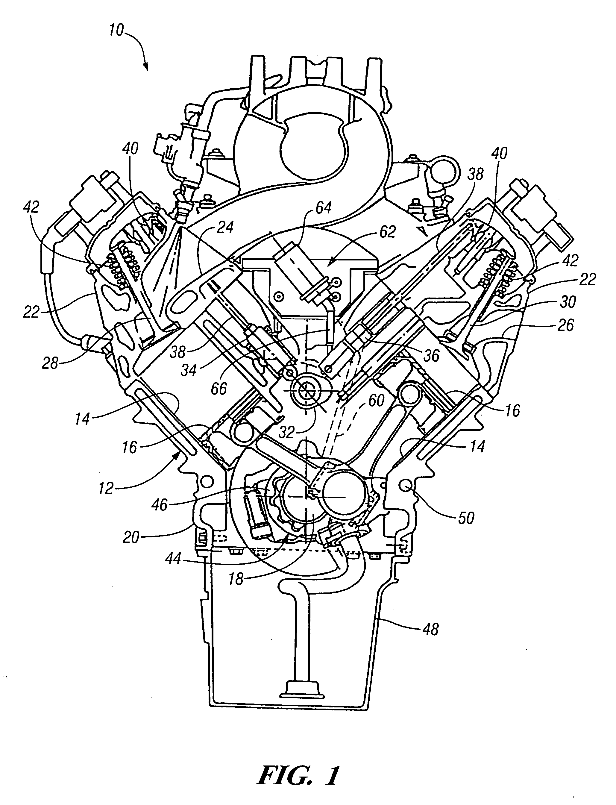
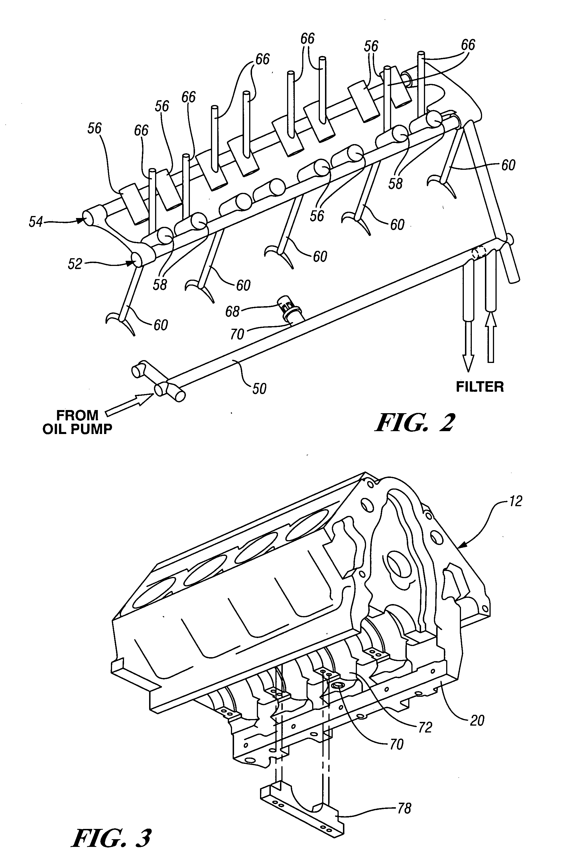
[0013] Referring first to FIG. 1 of the drawings, numeral 10 generally indicates a V8 automotive internal combustion engine. Engine 10 includes a cylinder block 12 having two banks of cylinders 14 containing pistons 16 reciprocated by rotation of a crankshaft 18 mounted in a crankcase portion 20 of the cylinder block 12. The cylinders are closed by cylinder heads 22 containing intake and exhaust passages 24, 26 controlled by intake and exhaust valves 28, 30, respectively.

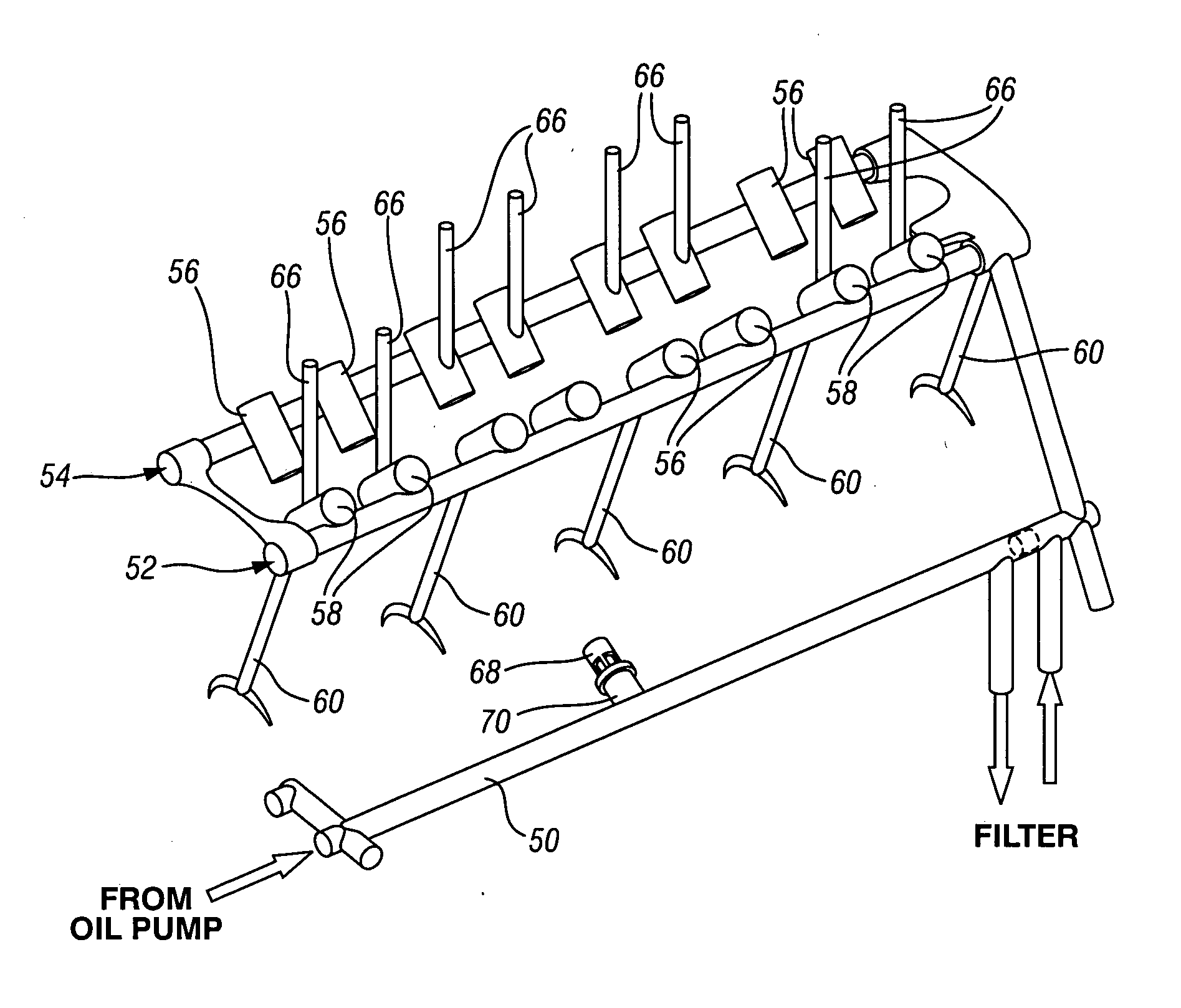
[0014] The valves are actuated by valve gear including a camshaft 32 driven by the engine crankshaft 18. The camshaft 32 actuates valve lifters including, both conventional roller hydraulic lifters 34 and so called switching lifters 36. The lifters engage push rods 38 which connect with rocker arms 40 to actuate the valves 28, 30 against the force of valve springs 42.

[0015] The engine 10 includes an oil lubrication and control system 44 shown in FIGS. 1-4. The oil system includes an oil pump 46 driven directly by ...


PUM


Abstract

An oil lubrication and control system, for an engine having cylinder deactivation switching lifters operated at the pressure of the full oil system, is provided with an auxiliary pressure relief valve which opens to control maximum oil pressure in the system whenever the engine speed and temperature conditions lie beyond the ability of the oil pump pressure control unit to maintain the maximum pressure limit. Addition of the auxiliary pressure relief valve allows extended operation of the switching lifters, which are limited by their construction to operation below a prescribed pressure limit. In a preferred embodiment, the auxiliary pressure relief valve is mounted in the engine crankcase in a bore connected directly with the main oil gallery to provide mounting and actuation of the auxiliary pressure relief valve with a minimum of modifications to the engine oil system design.

Description

CROSS REFERENCE TO RELATED APPLICATIONS [0001] This application claims the benefit of U.S. Provisional Application No. 60 / 498,266 filed Aug. 26, 2003.TECHNICAL FIELD [0002] This invention relates to a system and method for control of oil pressure in engines having cylinder deactivation hydraulic lifters. BACKGROUND OF THE INVENTION [0003] It is known in the art relating to engine cylinder deactivation to utilize so-called switching valve lifters responsive to an oil pressure signal to either maintain full operation of all the engine cylinders or deactivate the valves of cylinders having the switching lifters. This cuts out operation of these cylinders as a part of the engine power development process. Currently available switching lifters include a roller cam follower enclosing a hydraulic lash adjuster that is locked in place by a latch pin. When the lifter is in position to operate an associated engine valve, depression of the latch pin by an oil pressure signal allows the valve l...

Claims


Application Information

Patent Timeline
Patent Type & Authority Applications(United States)
IPC IPC(8): F01L1/14F01L1/245F01L1/34F01L13/00F01M1/00
CPCF01L1/146F01L13/0005F01L2001/0476F01L2810/02F01L2001/2427F01L2105/00F01L2001/054F01L2305/00
Inventor ROZARIO, FREDERICK J.ALBERTSON, WILLIAM C.HICKS, JAMES B.
Owner GM GLOBAL TECH OPERATIONS LLC
Why Eureka
Try Eureka