
Adjustable drywall mud applicator

Inactive Publication Date: 2005-03-03
KOOISTRA COMPANY L L C
View PDF9 Cites 13 Cited by
  • Summary
  • Abstract
  • Description
  • Claims
  • Application Information

AI Technical Summary

Benefits of technology

[0008] It is another object of the present invention to provide such an applicator that can be used to apply drywall mud to joints located on a straight wall section or to inside and outside corners.
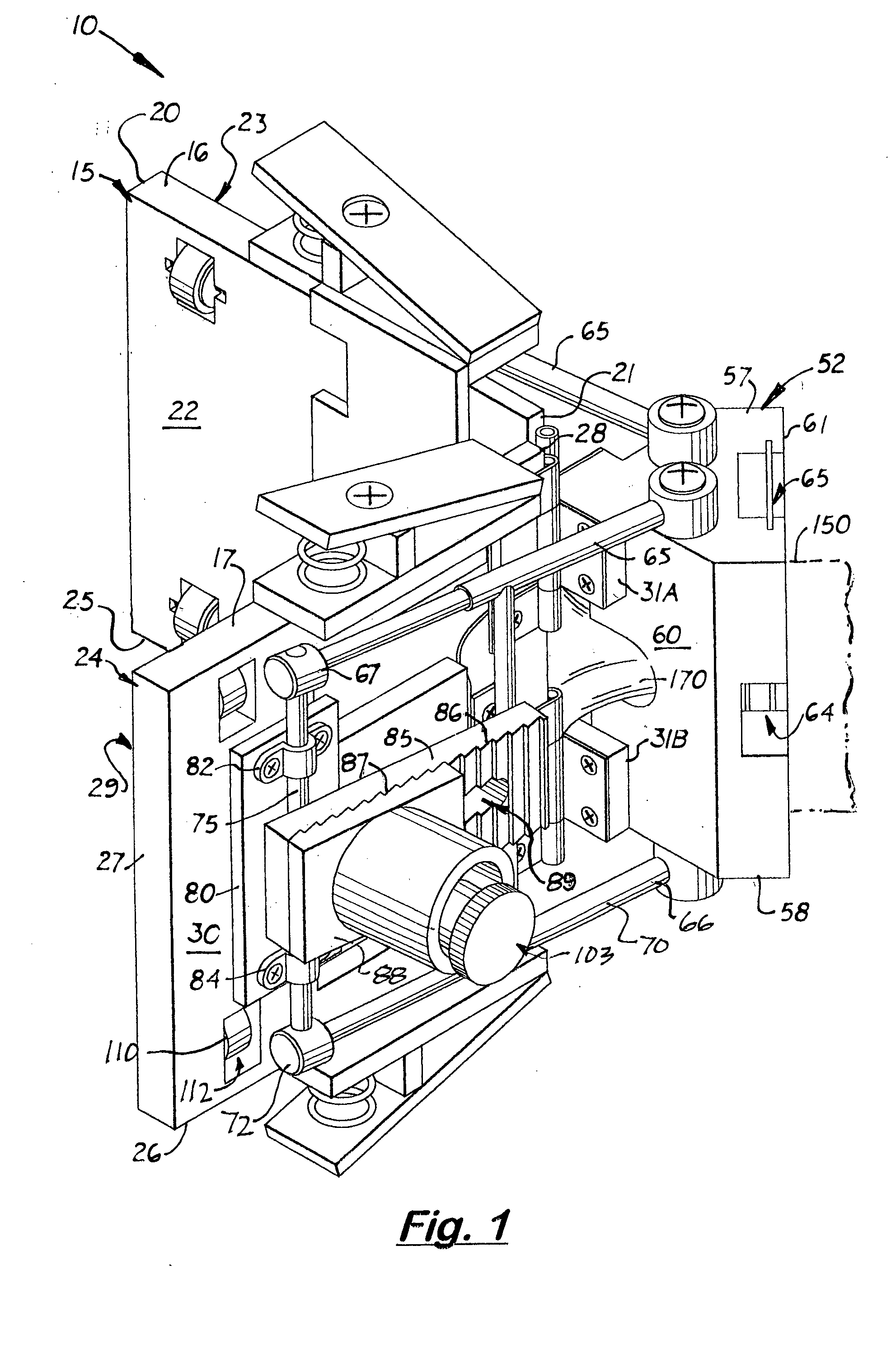
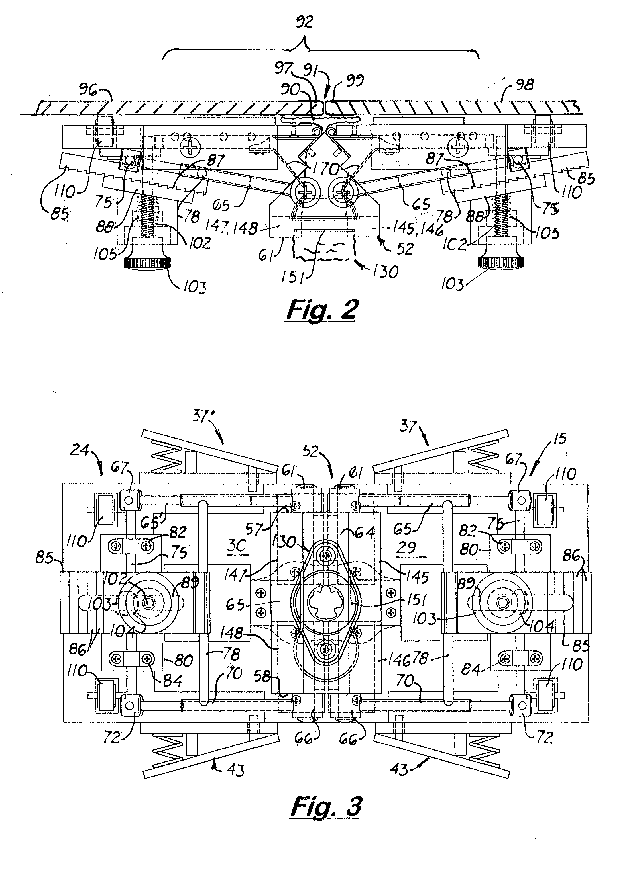
[0011] The applicator includes two side plates pivotally attached together along one edge, via hinges, to the opposite edges of an intermediate member. During use, the intermediate member is positioned centrally over the joint so that the two side plates are positioned against the two adjoining drywall panel surfaces on opposite sides of the joint to be covered with drywall tape. Mounted on the front surface of each side plate are two wheels that support the side plates a small distance above the drywall panel surface and allow the applicator to roll smoothly over the adjoining drywall panel surfaces when applying mud to the joint. Attached to each side plate is a guide member that slides laterally over the side plate's front surface to control the width of the mud applied to the drywall panel surface. A guide member locking mechanism is also provided for each guide member to selectively locking the guide plate in a desired position on the side plate. A linking assembly is also provided between the two side plates and the intermediate member that angularly aligns and locks the two side plates at a desired angle on opposite sides of the intermediate member.

Problems solved by technology

Because the initial layer of drywall mud must completely fill the gap and be applied in sufficient thickness to the edges on the adjacent panels, it is normally applied by hand, which is very time labor intensive.

Method used


Image

  • Adjustable drywall mud applicator
  • Adjustable drywall mud applicator
  • Adjustable drywall mud applicator

Examples


Embodiment Construction

)

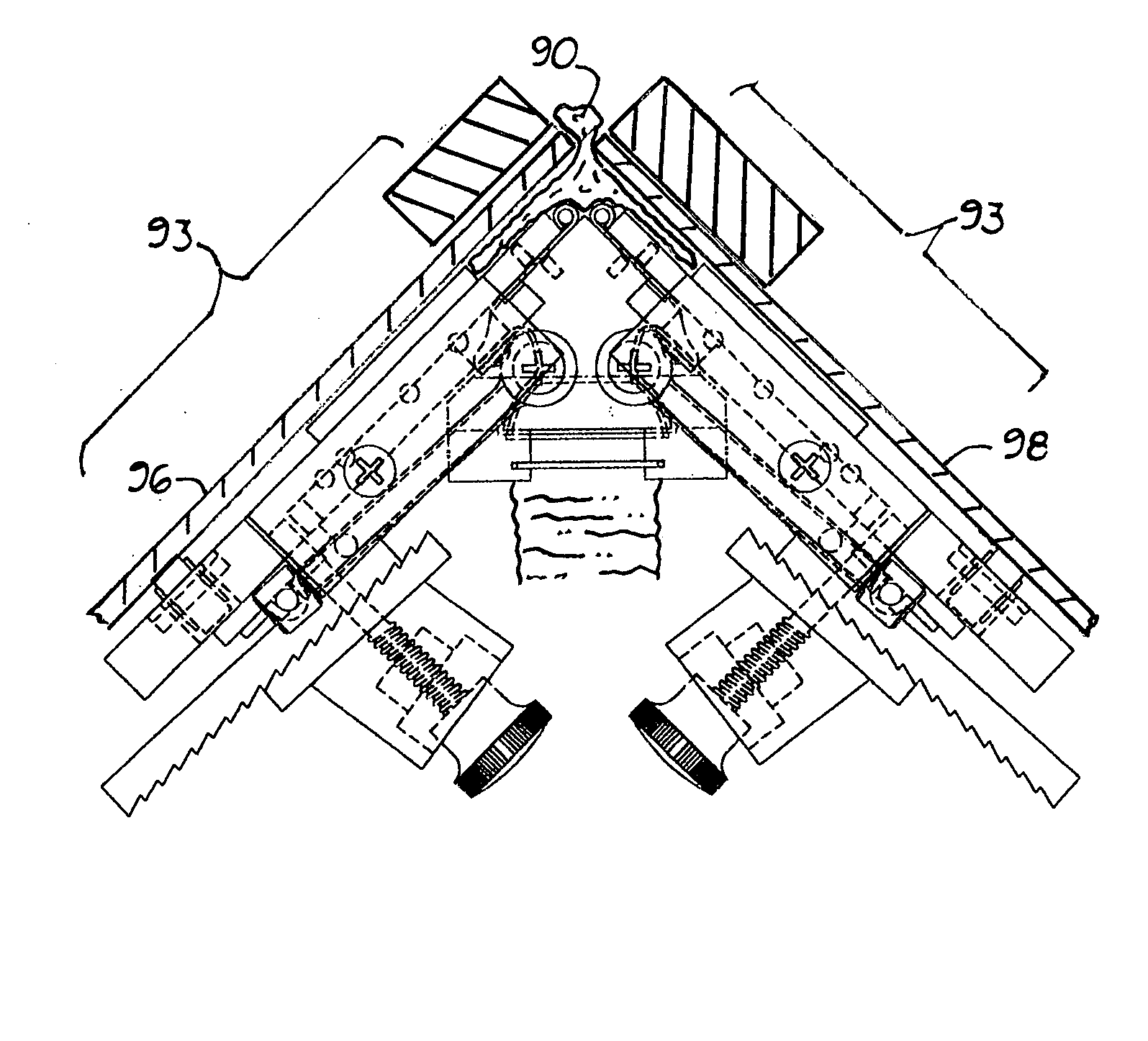
[0024] There is shown in the accompanying Figures a drywall corner mud applicator, generally referred to as 10, designed to continuously and easily apply an initial layer of mastic material, hereinafter called mud 90, to a joint 91 between two adjacent drywall panels 96, 97 located on a straight wall 92 as shown in FIG. 2, on an inside corner 93 as shown in FIG. 7 or on an outside corner 94 as shown in FIG. 10. The layer of mud 90 is sufficiently thick to fill the joint 91 and sufficiently wide to cover the perimeter edges 96, 99 of the adjoining drywall panels 96, 98, respectively. After the mud 90 is applied to the joint 91, drywall tape 100 may then be applied over the joint 91. The main purpose of the applicator 10 is to quickly and easily apply a thick, uniform layer of mud 90 directly into the joint 91 and over the perimeter edges 97, 99 of the drywall panels 96, 98, respectively.

[0025] The applicator 10 includes two side plates 15, 24 pivotally attached to the opposite side...


PUM


Abstract

A drywall mud applicator, designed to quickly and easily apply a first layer of mud or mastic material to a joint in preparation for applying drywall tape thereto. The applicator includes a main housing comprising two side plates pivotally connected to an intermediate member. During use, the side plates are centrally aligned over a joint located between adjacent drywall panels so that each side plate is positioned against the adjoining drywall surface. The intermediate member is longitudinally aligned over the longitudinal axis of the joint. Attached to each side plate is a guide member that slides laterally over the side plate's front surface to control the width of the mud applied to the joint. A guide plate locking mechanism is provided for selectively locking the guide members in a desired position on the two side plates. A bellows is connected to the intermediate member and is used to evenly distribute mud to port openings formed on the two side plates.

Description

BACKGROUND OF THE INVENTION [0001] 1. Field of the Invention [0002] This invention relates generally to drywall mud applicators and more particularly, to applicators that are adjustable for applying mud to joints located between drywall panels. [0003] 2. Description of the Related Art [0004] When drywall is mounted on a wall, a joint is created that is covered by drywall flex and rigid finishing material, including drywall paper tape. The drywall tape is applied over a thin layer of drywall mud applied inside the gap and over the adjoining edges of the drywall panels. Ideally, the layer of drywall mud should be sufficiently wide to completely fill the gap between drywall panels and to cover the areas under the tape to insure bonding of the backside of the drywall tape to the panels. The drywall mud should also be sufficiently thick to bond the tape to the wall. [0005] Drywall panels are installed so that the vertical and horizontal joints are aligned. Because the initial layer of dr...

Claims


Application Information

Patent Timeline
IPC IPC(8): E04F21/08
CPCE04F21/165E04F21/08E04F21/1655
Inventor KOOISTRA, RUSS
Owner KOOISTRA COMPANY L L C
Learn More