Axial tube assembly for a motor

a technology of axial tube and motor, which is applied in the direction of dynamo-electric machines, magnetic circuit shape/form/construction, structural associations, etc., can solve the problems of noise generation and uneven rotation, and achieve the effect of reliable positioning of the bearing of the motor

Inactive Publication Date: 2005-03-03
SUNONWEALTH ELECTRIC MACHINE IND
View PDF4 Cites 26 Cited by
  • Summary
  • Abstract
  • Description
  • Claims
  • Application Information

AI Technical Summary

Benefits of technology

[0006] An object of the present invention is to provide an axial t...

Problems solved by technology

As a result, the rotational stability is adversely affec...

Method used


Image

  • Axial tube assembly for a motor
  • Axial tube assembly for a motor
  • Axial tube assembly for a motor

Examples


Embodiment Construction

[0031] Preferred embodiments of the present invention are now to be described hereinafter in detail, in which the same reference numerals are used in the preferred embodiments for the same parts as those in the prior art to avoid redundant description.

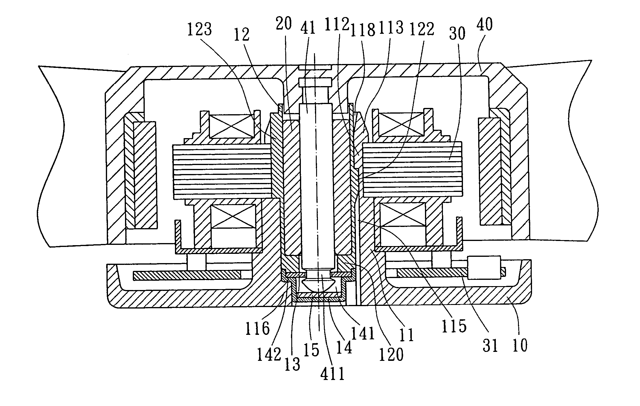
[0032] Referring to FIGS. 3 through 5, a first embodiment of an axial tube assembly for a motor in accordance with the present invention includes an axial tube 11 and a sleeve 12. The axial tube 11 can be mounted to a casing 10 and engaged with a bearing 20, a stator 30, a circuit board 31, and a rotor 40, thereby forming a motor such as a miniature brushless D.C. motor, as shown in FIG. 6.

[0033] The axial tube 11 is preferably made of a plastic material and includes plurality of engaging blocks 111 on a lower end of an outer periphery thereof. A plurality of protrusions 116 are formed on a lower end of an inner periphery of the axial tube 11. Preferably, the protrusions 116 are spaced by regular intervals and symmetrically disposed....


PUM


Abstract

An axial tube assembly for a motor includes an axial tube and a sleeve mounted in the axial tube. The axial tube is securely mounted to a casing, and a stator is mounted to the axial tube. The axial tube includes at least one engaging member on an inner periphery thereof. The sleeve includes at least one engaging member engaged with the engaging member of the axial tube. When a bearing is mounted in the sleeve, the sleeve is tightly engaged with the axial tube such that the axial tube and the bearing exert forces to each other to thereby retain the axial tube and the bearing in place.

Description

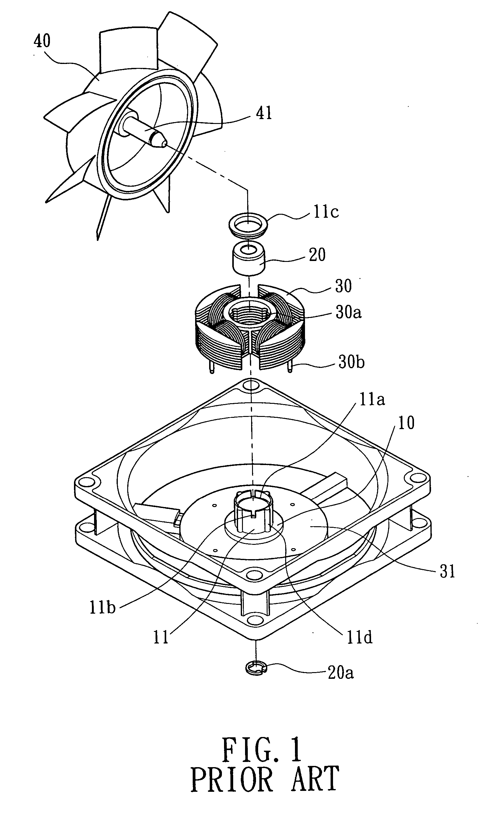
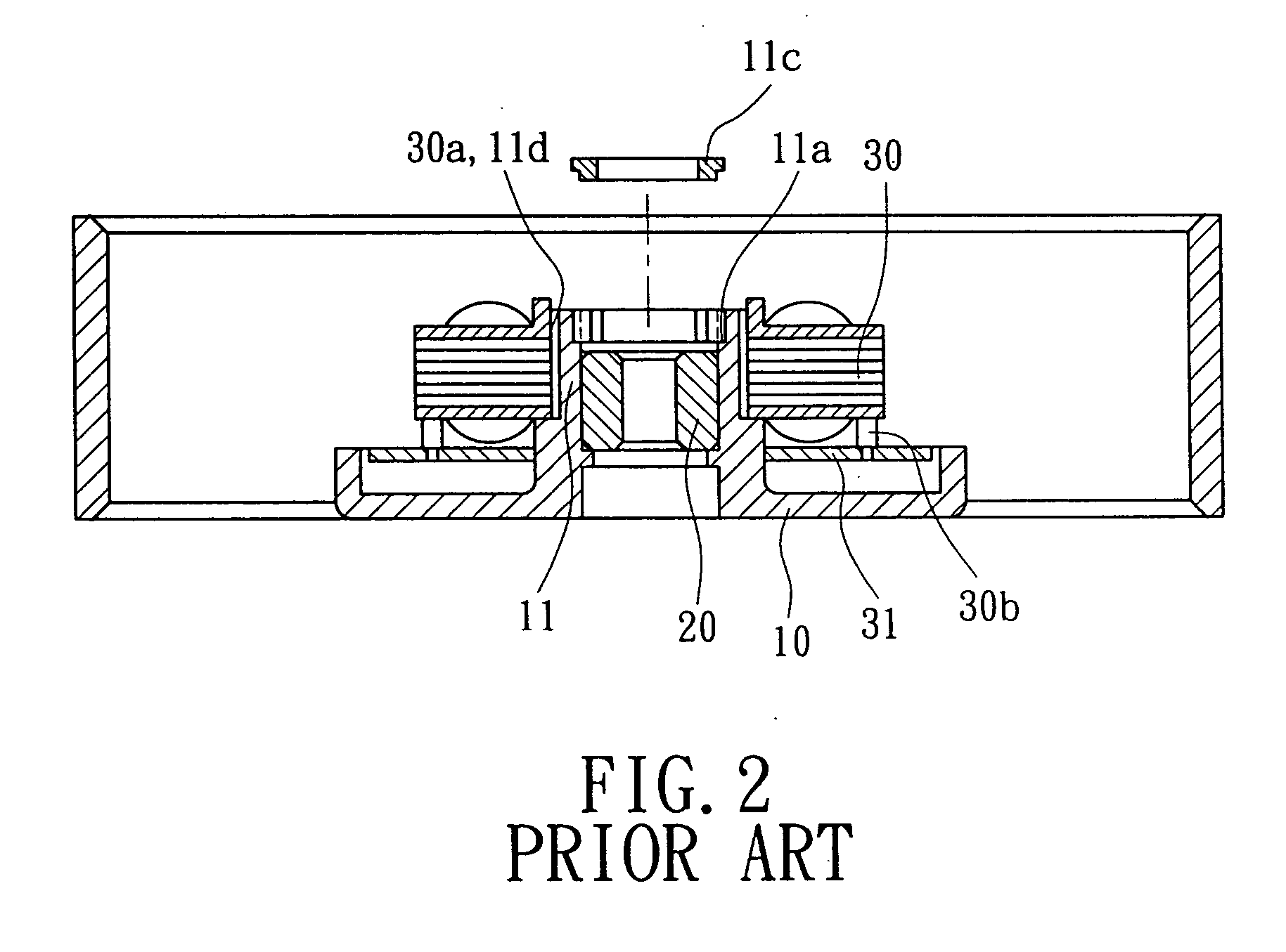
BACKGROUND OF THE INVENTION [0001] 1. Field of the Invention [0002] The present invention relates to an axial tube assembly for a motor. In particular, the present invention relates to an axial tube assembly for reliably positioning a bearing of a motor. The present invention also relates to a motor having such an axial tube assembly. [0003] 2. Description of Related Art [0004]FIGS. 1 and 2 of the drawings illustrate a conventional motor including a casing 10, a bearing 20, a stator 30, a circuit board 31, and a rotor 40. The casing 10 includes an axial tube 11 integrally formed on a central portion of the casing 10. The axial tube 11 includes a stepped portion 11a on an inner periphery thereof and a plurality of longitudinal slits 11b in a top end thereof. The slits 11b allow the axial tube 11 to expand radially outward. After the bearing 20 is mounted into the axial tube 11, a retaining cap 11c is mounted to the stepped portion 11a to improve assembling reliability, and a shaft 41...

Claims


Application Information

Patent Timeline
IPC IPC(8): H02K1/18H02K5/167
CPCH02K5/1675H02K1/187
Inventor HORNG, ALEXHONG, YIN-RONGHONG, CHING-SHENG
Owner SUNONWEALTH ELECTRIC MACHINE IND
Why Eureka
Try Eureka