Linear type actuator

Inactive Publication Date: 2005-03-03
MINEBEAMITSUMI INC
View PDF12 Cites 24 Cited by
  • Summary
  • Abstract
  • Description
  • Claims
  • Application Information

AI Technical Summary

Benefits of technology

[0011] The present invention was made considering the above problems, and it is an object of the present invention to provide a linear type actuator in which a rotor unit is manufactured by insert molding a nut serving

Problems solved by technology

Since the female screw 52 is required to feature small coefficient of friction, high wear resistance and excellent dimensional stability, insert molding thereof requires a high-quality and therefore expensive resin material pushing up the cost.
Furthermore, since its molding conditions include high temperature and high pressure, the workability of insert molding the female screw 52 together with the field magnet 51 is deteriorated and the insert molded product

Method used


Image

  • Linear type actuator
  • Linear type actuator
  • Linear type actuator

Examples


Example

[0022] The present invention will now be described by reference to the accompanying drawings.

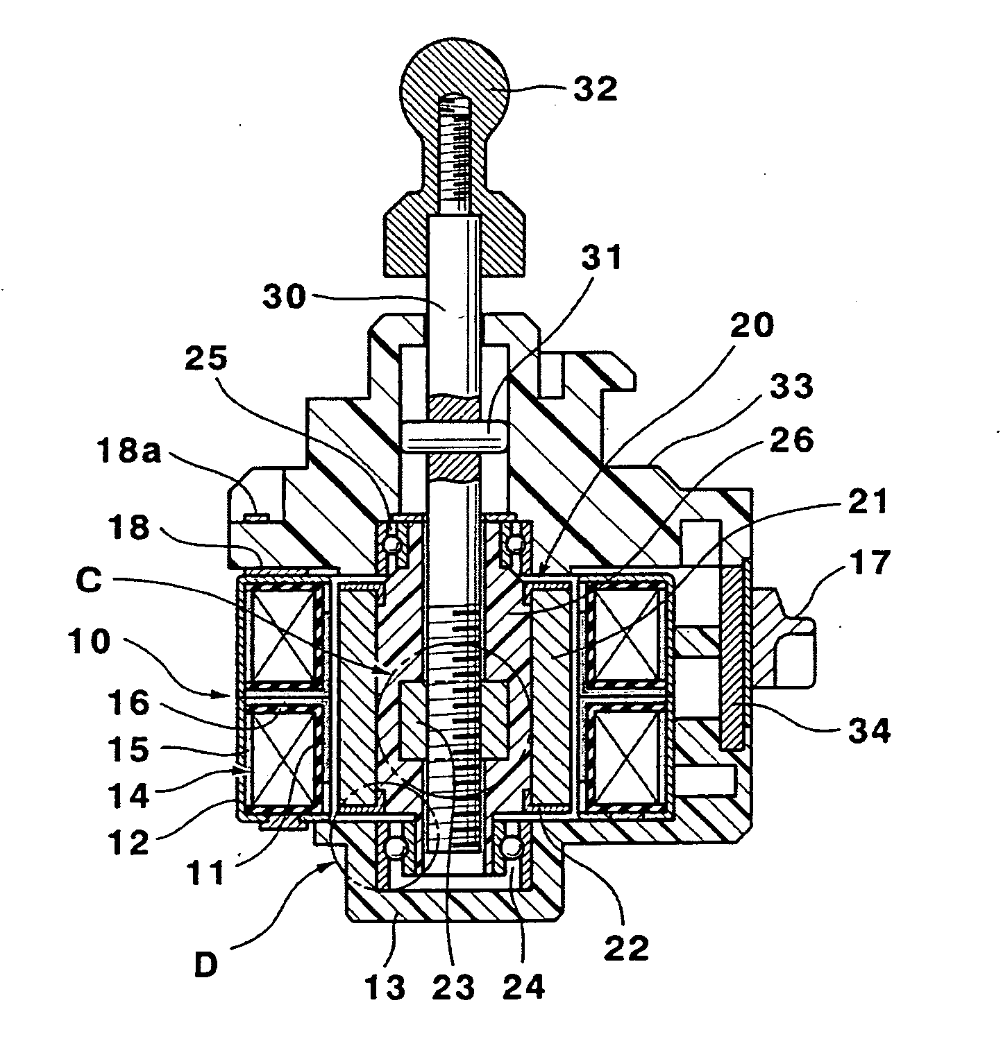
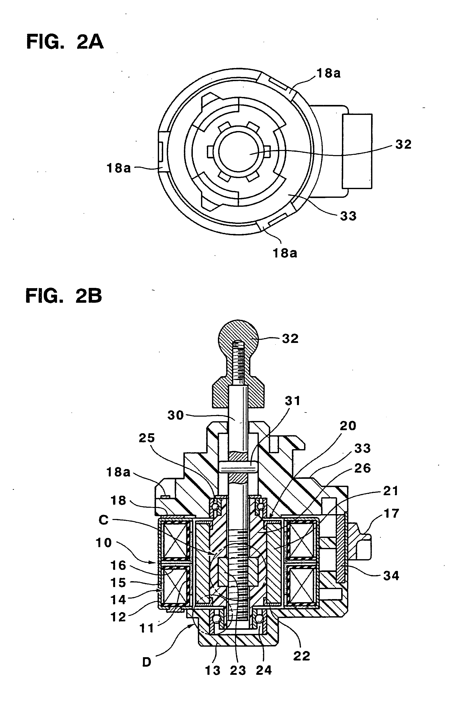
[0023]FIG. 2A shows a top plan view of the entire structure of a linear type actuator using a PM stepping motor according to the present invention, and FIG. 2B shows a longitudinal sectional view of the linear type actuator shown FIG. 2A taken along line A-A.

[0024] A stator unit 10 comprises two stator sub-assemblies 12 attached to each other in a back to back manner to form two layer construction and integrally molded with a resin material. Each stator sub-assembly 12 is constructed by two kinds of stator yokes formed of a soft magnetic steel sheet worked by sheet metal processing so as to have pole teeth 11 on the inner circumference and to house a coil 14. In this integral molding process, a rear plate 13 which constitutes one end face of the stator unit 10 and has a bearing in its central portion is formed by a resin material for integration at the same time. Thus, a high coaxial preci...


PUM

PropertyMeasurementUnit
Abrasion resistanceaaaaaaaaaa
Friction coefficientaaaaaaaaaa

Abstract

In order to reduce cost through reduction in material cost and improvement of productivity, in a linear type actuator comprising: a stator unit having coils consisting of wound magnet wires and housed inside stator sub-assemblies and pole teeth arranged on the inner circumference thereof; a rotor unit having a field magnet arranged on the outer circumference thereof and rotatably disposed so as to oppose the pole teeth with a given gap; an output shaft attached to a center portion of the rotor unit and movble in the axial direction thereof; and converting means provided on the innermost diametral circumferential surface of the rotor unit and adapted to convert rotary motion of the rotor unit into linear motion of the output shaft, the converting means is made of a material different from that of the rotor unit.

Description

[0001] In order to reduce cost through reduction in material cost and improvement of productivity, in a linear type actuator comprising: a stator unit having coils consisting of wound magnet wires and housed inside stator sub-assemblies and pole teeth arranged on the inner circumference thereof; a rotor unit having a field magnet arranged on the outer circumference thereof and rotatably disposed so as to oppose the pole teeth with a given gap; an output shaft attached to a center portion of the rotor unit and movable in the axial direction thereof; and converting means provided on the innermost diametral circumferential surface of the rotor unit and adapted to convert rotary motion of the rotor unit into linear motion of the output shaft, the converting means is made of a material different from that of the rotor unit. BACKGROUND OF THE INVENTION [0002] 1. Field of the Invention [0003] The present invention relates to a linear type actuator, in which an output shaft is adapted to mo...

Claims


Application Information

Patent Timeline
IPC IPC(8): F16H25/24H02K7/06
CPCH02K7/06Y10T74/18664Y10T74/18576Y10T29/49012
Inventor SUZUKI, YUZURUFUJITANI, SAKAEHARADA, NAOYUKIMATSUSHITA, KUNITAKE
Owner MINEBEAMITSUMI INC
Why Eureka
Try Eureka