

Vacuum evaporation device
- Summary
- Abstract
- Description
- Claims
- Application Information
AI Technical Summary
Benefits of technology
Problems solved by technology
Method used
Image

Examples
Embodiment Construction
[0058]The following description of the various embodiments is provided to illustrate the specific embodiments of the invention. Directional terms mentioned in this application, such as “up,”“down,”“forward,”“backward,”“left,”“right,”“inside,”“outside,”“side,” etc., are merely indicated the direction of the drawings. Therefore, the directional terms are used for illustrating and understanding of the application rather than limiting thereof. In the drawings, structurally similar elements are denoted by the same reference numerals.
[0059]The present invention is capable of solving the technical problem in the conventional vacuum evaporation such as a slow recycling rate, a long opening time, an increase in the number of particles, and contamination of the cavity.
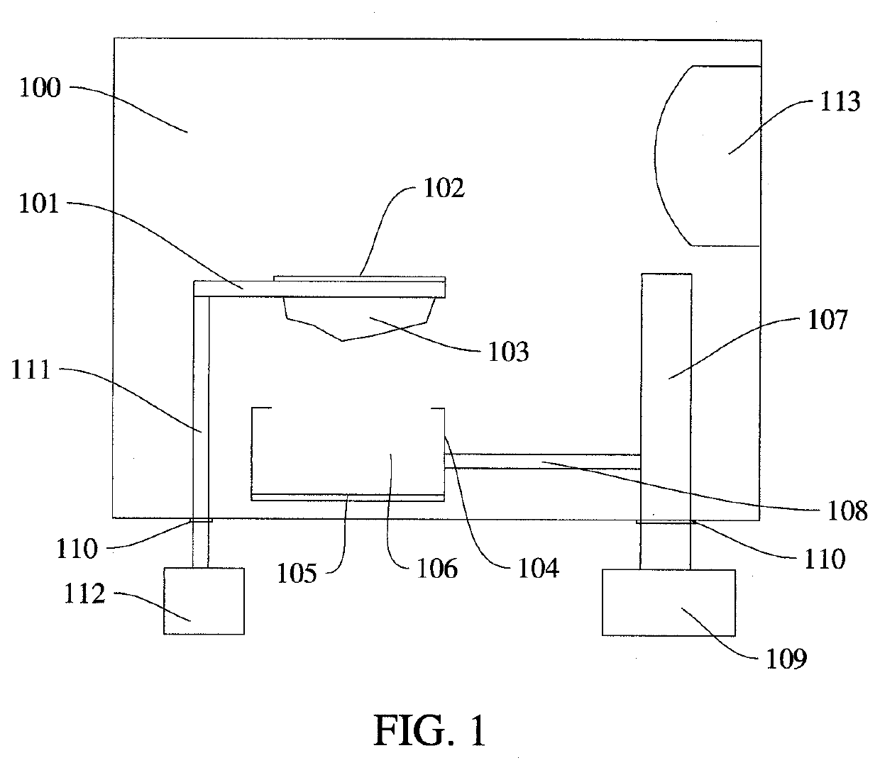
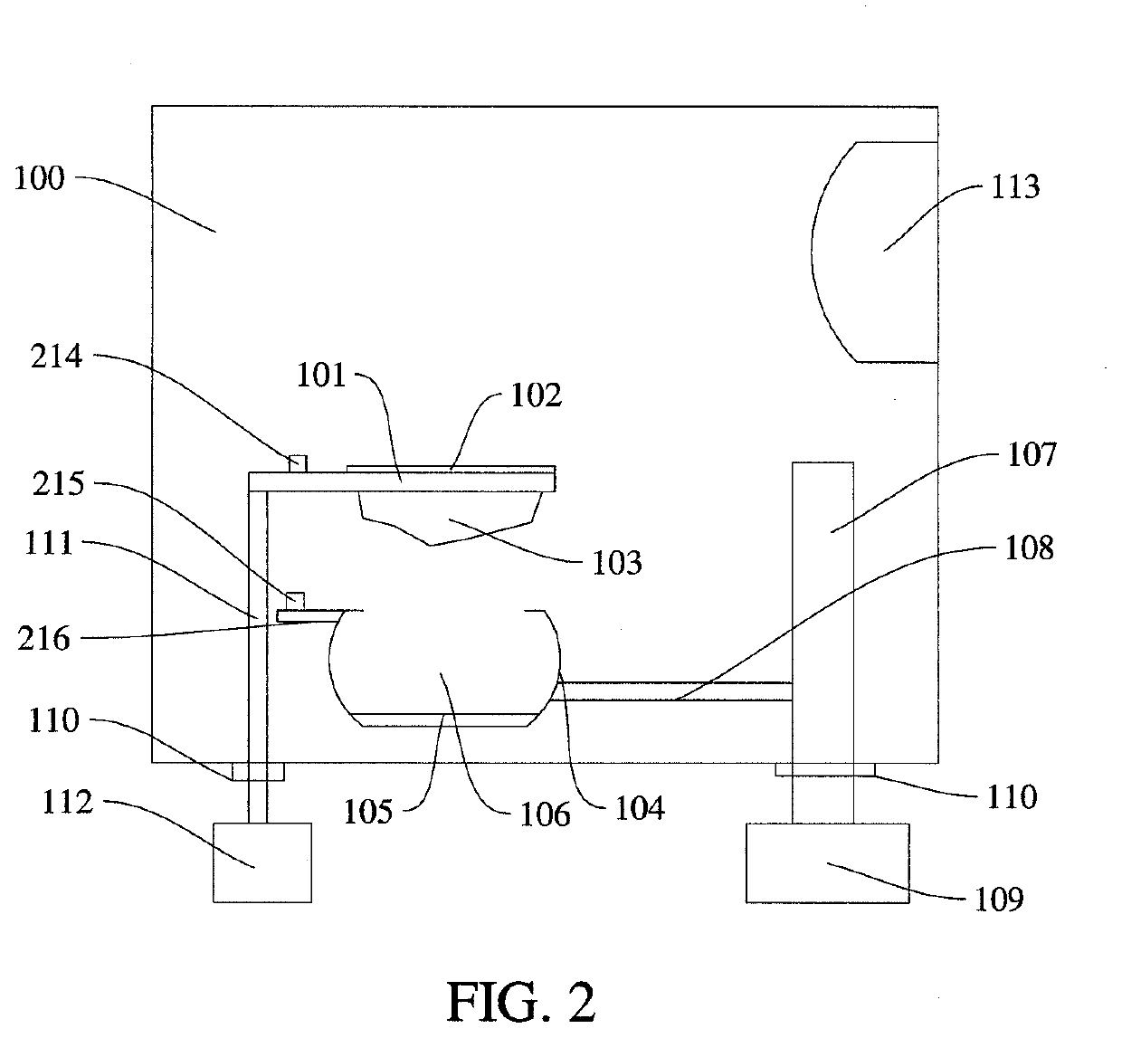
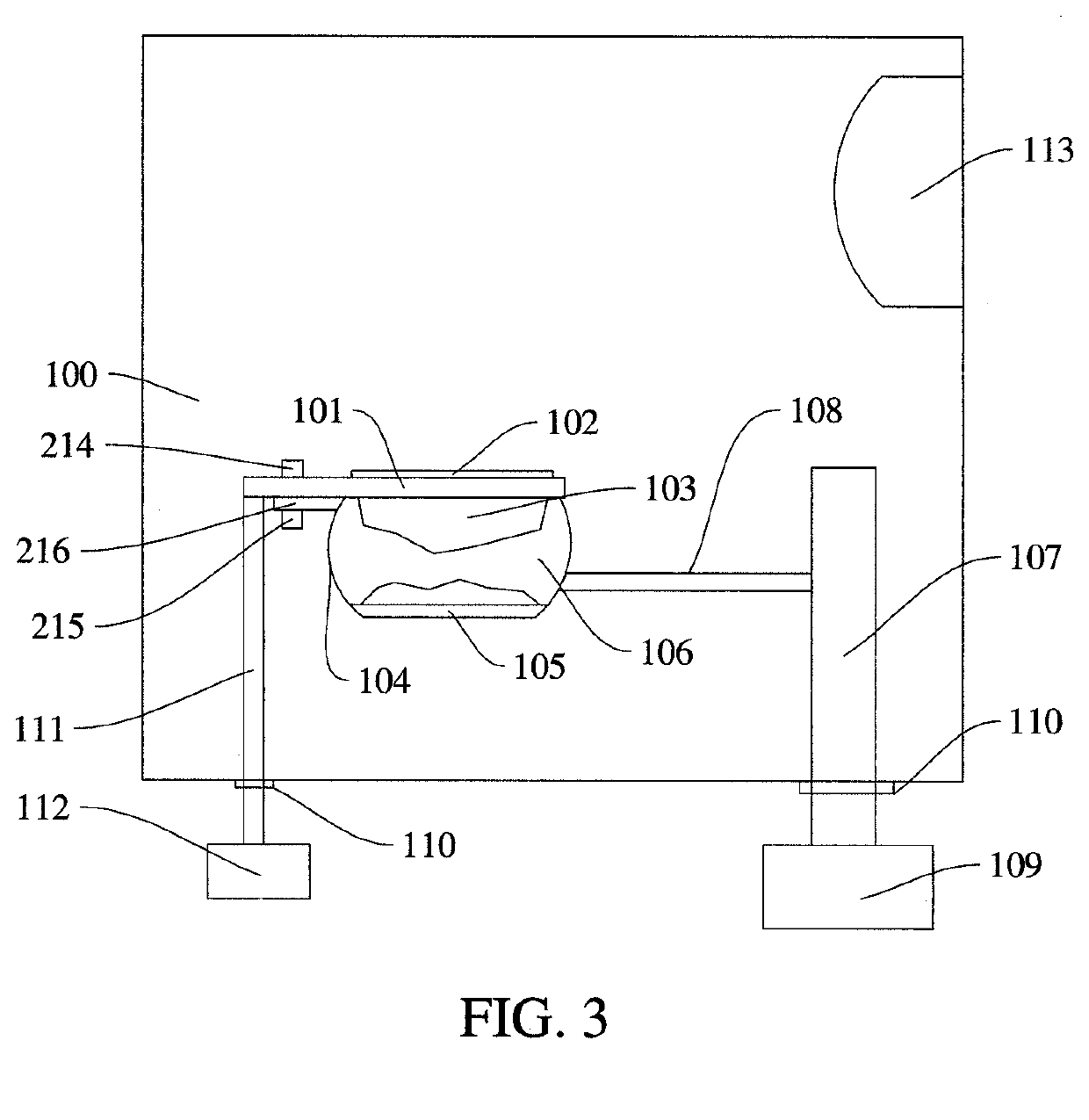
[0060]Referring to FIG. 1, in one embodiment, a vacuum evaporation device is provided. The vacuum evaporation device includes an evaporation chamber 100 formed by interconnecting a top plate, a bottom plate and a plurality of si...
PUM
 Abstract
Description
Claims
Application Information