

Autostereoscopic display for multiple viewers
- Summary
- Abstract
- Description
- Claims
- Application Information
AI Technical Summary
Benefits of technology
Problems solved by technology
Method used
Image

Examples
Embodiment Construction
[0036] The present description is directed in particular to elements forming part of, or cooperating more directly with, apparatus in accordance with the invention. It is to be understood that elements not specifically shown or described may take various forms well known to those skilled in the art.
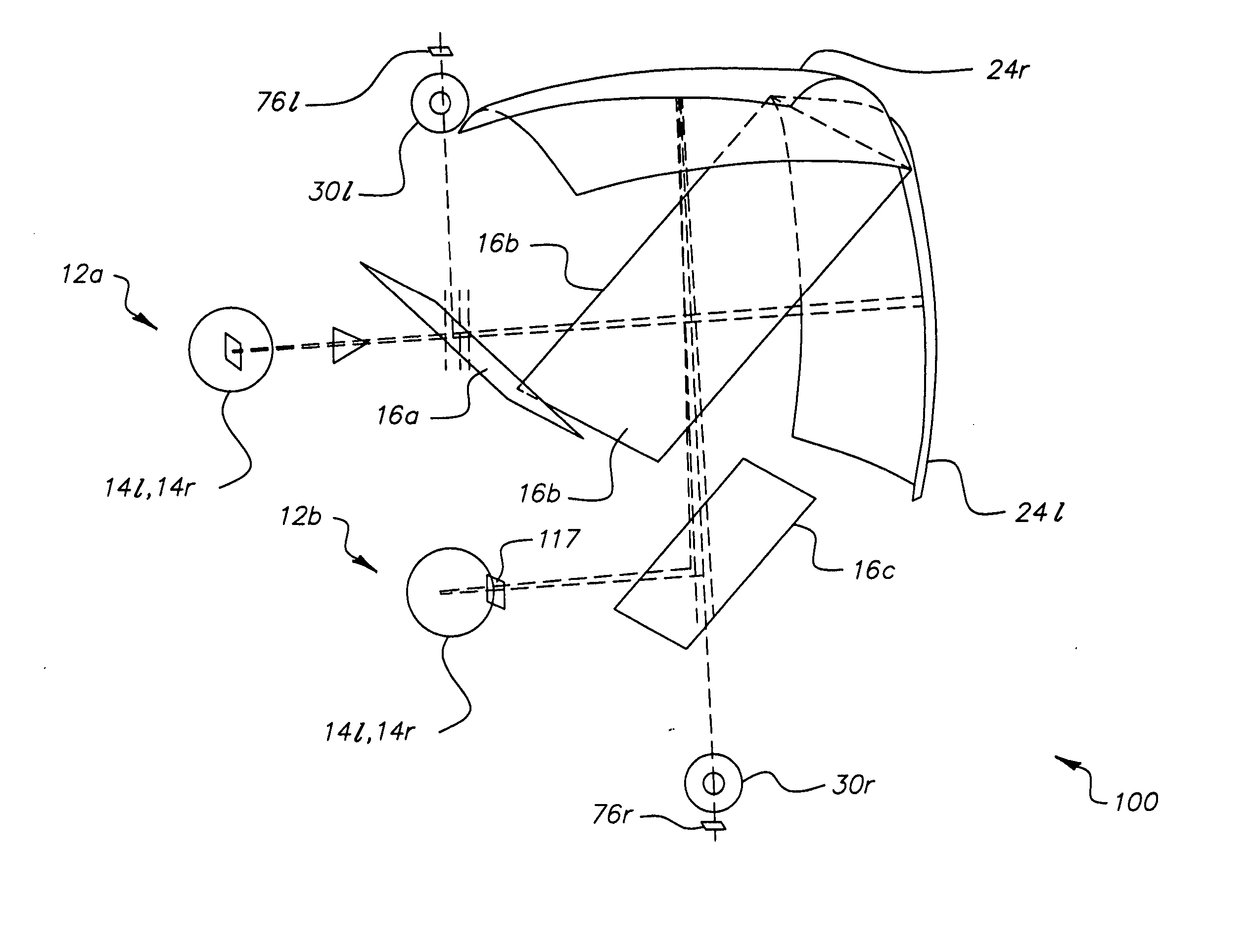
[0037] The disclosure of U.S. Pat. Nos. 6,416,181 and 6,755,532 (Cobb) and U.S. patent application Ser. No. 10 / 465,503 give detailed information on how an intermediate image can be formed using a linear or an area spatial light modulator. The description of the present invention that follows concerns itself with the optical path that, given these left and right intermediate images, forms left and right virtual images in order to provide an apparatus allowing multiple viewers.
Embodiments with Multiple Curved Mirrors 24
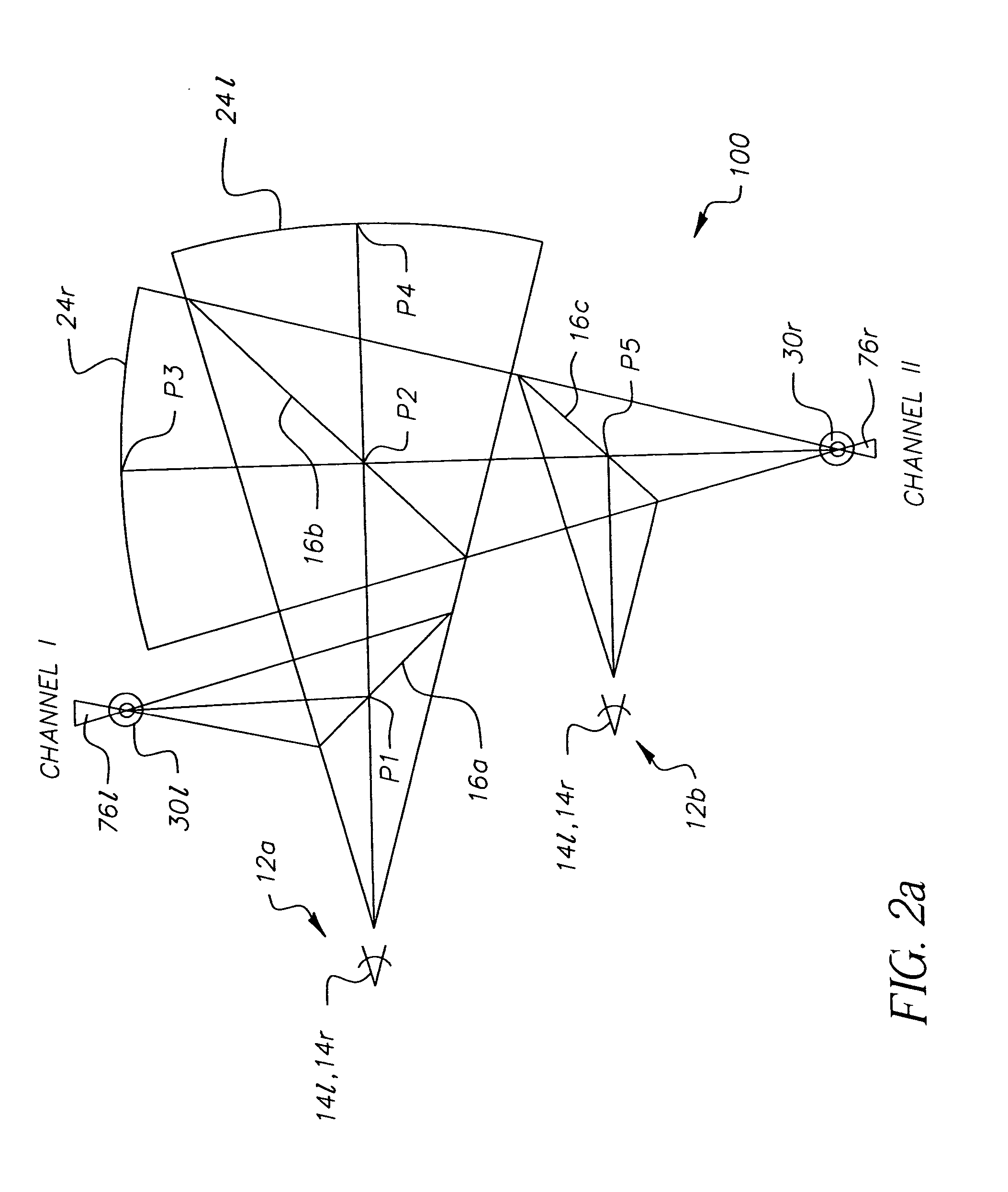
[0038] Referring to FIG. 2a, there is shown, in side-view schematic form, an embodiment of a multi-viewer autostereoscopic imaging apparatus 100 employing a left curved mir...
PUM
 Abstract
Description
Claims
Application Information