DC-DC converter

a dc-dc converter and converter technology, applied in the direction of electric variable regulation, process and machine control, instruments, etc., can solve the problems of increasing the cost large size of capacitors cb>101/b>, and the upsizing of dc to dc voltage converter systems, so as to reduce the amount of ripple components contained

Active Publication Date: 2005-03-03
DENSO CORP +1
View PDF6 Cites 86 Cited by
  • Summary
  • Abstract
  • Description
  • Claims
  • Application Information

AI Technical Summary

Problems solved by technology

The large capacitance capacitor C101 is of large size and expensive, causing the DC to DC voltage converter system to be upsized and the cost thereof to increase.
The increased ripple components may also increase an effective value of the input current, which may result in increasing loss of energy and heating value of the DC to DC converter system.

Method used


Image

  • DC-DC converter
  • DC-DC converter
  • DC-DC converter

Examples


first embodiment

[0070] [First Embodiment]

[0071] (Whole Structure of a DC to DC Converter)

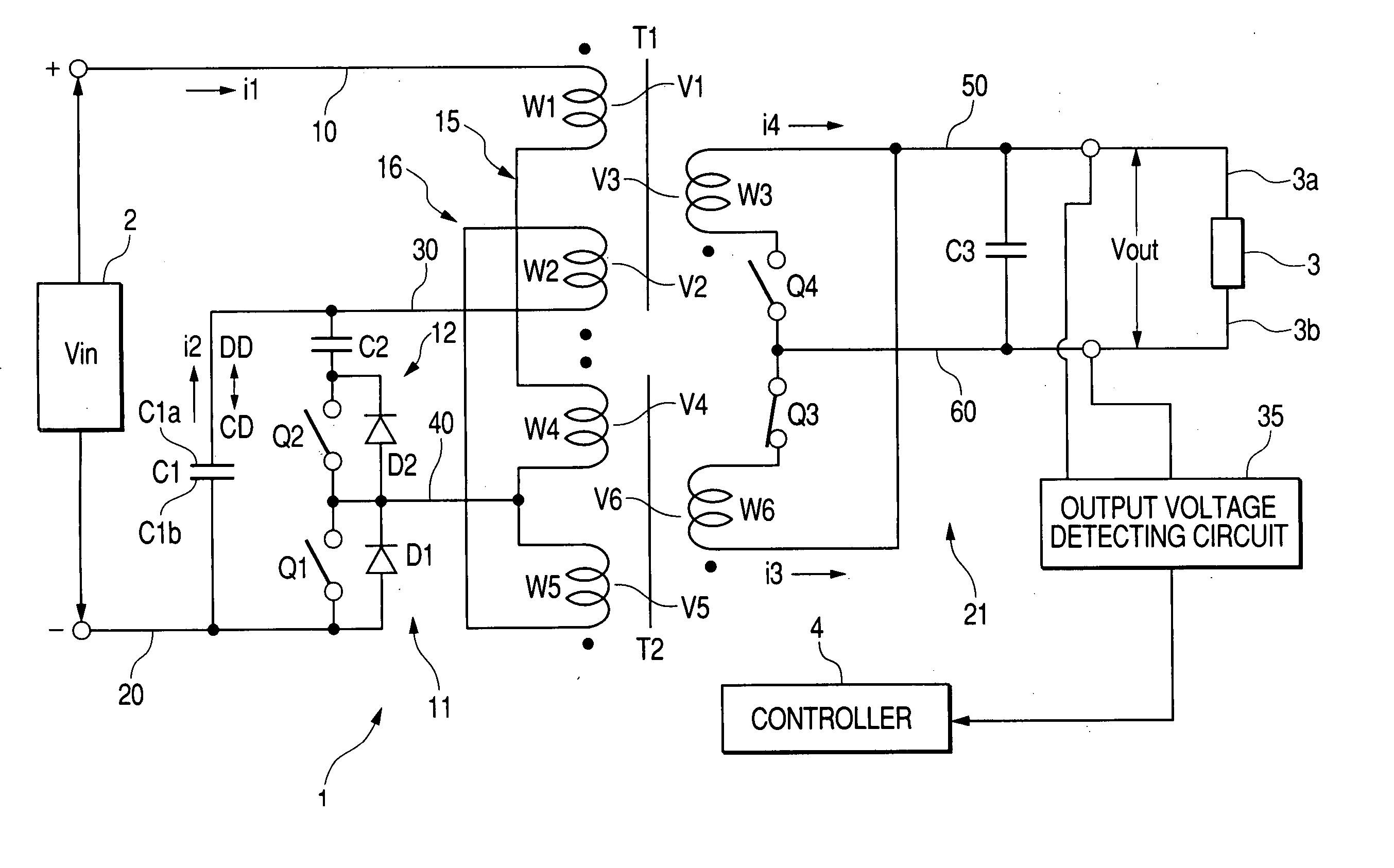
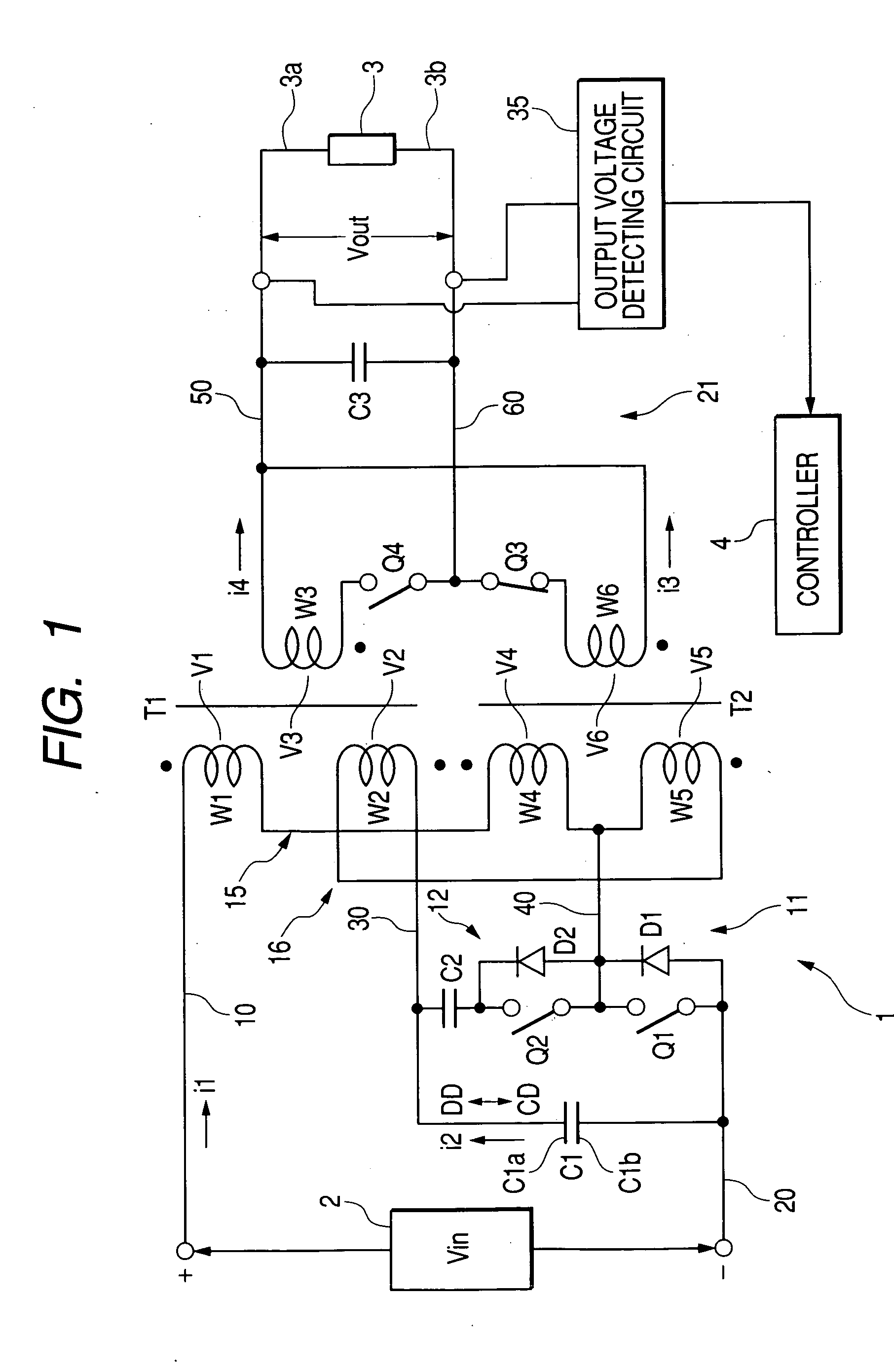
[0072] The whole structure of a DC to DC converter according to a first embodiment will be explained in accordance with FIG. 1.

[0073] The DC to DC converter 1 is served as a unidirectional step down converter, the input side of which is coupled to a high-voltage input DC power supply 2, as a first voltage system. The output side of the DC to DC converter 1 is coupled to a low-voltage load 3, as a second voltage system.

[0074] As the DC to DC converter 1, a unidirectional step up converter may be used, and as the low-voltage load 3, a low-voltage power supply for supplying a DC voltage lower than the high DC voltage may be used.

[0075] The DC to DC converter 1 includes a first transformer assembly T1, a second transformer assembly T2, and a first converting circuit 11. The first converting circuit 11 includes a first switching element Q1, a first capacitor C1, and a clamp circuit 12. The clamp circuit 12 consi...

second embodiment

[0205] [Second Embodiment]

[0206] A DC to DC converter according to a second embodiment of the present invention will be described in accordance with FIG. 10. In the second embodiment, the controller 4 of the DC to DC converter controls the on duty ratio of the first switching element Q1 within a predetermined range X centered at 50 percents, such as 40 to 60 percents. The DC to DC converter is used for applications which does not require a wide range of the on duty ratio.

[0207] This structure of the DC to DC converter according to the second embodiment allows the ripple components contained in the output current io (i3+i4) to be reduced less than a predetermined percents, such as 10 percents (see FIG. 10). The ratio (percents) of the ripple components contained in the output current io have a characteristic that continuously varies depending on the on duty ratio of the first switching element Q1 (see FIG. 10). The predetermined value of the on duty ratio corresponding to the minimu...

third embodiment

[0209] [Third Embodiment]

[0210] A DC to DC converter according to a third embodiment of the present invention will be described in accordance with FIG. 11. In the third embodiment, the DC to DC converter 1B is served as a bidirectional DC to DC converter.

[0211] That is, the DC to DC converter 1B has a primary circuit (PC) 300 for the transformer assemblies T1 and T2, which corresponds to the circuit composed of the capacitors C1, C2, the switching elements Q1, Q2, and the connections thereamong, the transformer assemblies T1 and T2, and the input DC power supply 2. The DC to DC converter 1B also has a synchronous rectifying circuit (SC) 400, which corresponds to the circuit composed of the switching elements Q3, Q4, the capacitor C3, and the connections thereamong, the transformer assemblies T1 and T2, and the load, such as a power supply 3.

[0212] The DC to DC converter 1B has a controller 500 corresponding to the controller 4 shown in FIG. 1, and a driver 600 connected between ea...


PUM


Abstract

In a DC to DC converter, first and second primary windings are magnetically coupled to a first secondary winding. Third and fourth primary windings are magnetically coupled to a second secondary winding. The first and second primary windings are magnetically coupled to the first secondary winding. The third and fourth primary windings are magnetically coupled to the second secondary winding. The first and third primary windings are coupled in series to form a first coil member. The second and fourth primary windings are coupled in series to form a second coil member. One end of the first coil member is coupled to the first positive power line. A first switching element is coupled between the first negative power line and the other end of the first coil member. A first capacitor is coupled between the first negative terminal and one end of the second coil member.

Description

CROSS REFERENCE TO RELATED APPLICATION [0001] This application is based upon and claims the benefit of priority of the prior Japanese Patent Application 2003-275643 filed on Jul. 16, 2003 so that the contents of which are incorporated herein by reference. BACKGROUND OF THE INVENTION [0002] 1. Field of the Invention [0003] The present invention relates to an improved DC (direct current) to DC converter. [0004] 2. Description of the Related Art [0005] DC to DC converters each with a transformer are capable of isolating between input and output thereof so that they have been widely used. In transformer DC to DC converters, various types of them each having two transformers have been well-known. [0006] For one example, Japanese Unexamined Patent Publication No. 2003-102175 discloses a DC to DC converter system including two DC to DC converters. Each of the DC to DC converters has a substantially conventional structure with one transformer. The two DC to DC converters are connected to ea...

Claims


Application Information

Patent Timeline
Patent Type & Authority Applications(United States)
IPC IPC(8): H02M3/335
CPCH02M3/33569Y02B70/1475H02M3/33592Y10S323/908Y02B70/10H02M3/01
Inventor KAWASAKI, KOJISHIGEOKA, KEIJIYAMASHITA, TSUYOSHI
Owner DENSO CORP
Why Eureka
Try Eureka