Optical disc apparatus and spherical aberration correction controlling apparatus

a technology of optical discs and control apparatuses, applied in the direction of digital signal error detection/correction, instruments, recording signal processing, etc., can solve the problems of spherical aberration, lowering recording/recording performance, not negligible, etc., to prevent a reduction in recording/recording performance and high reliability

Inactive Publication Date: 2005-03-03
PANASONIC CORP
View PDF5 Cites 21 Cited by
  • Summary
  • Abstract
  • Description
  • Claims
  • Application Information

AI Technical Summary

Benefits of technology

Thus, the invention described herein makes possible the advantage of providing an optical disc apparatus and a spherical aberration correction controlling apparatus, in which spherical ...

Problems solved by technology

As a result, reproduction/recording performance is lowered.
Thus, particularly when an optical lens having a large numerical aperture (NA) of 0.8 or more is used, spherical aberration, which occurs due to the uneven thickness of a protection layer for protecting the information surface of an optical disc and errors in the distance between the surface of a multi-layer optical disc and the information surface of each layer, is not negligible.
However, in the conventio...

Method used


Image

  • Optical disc apparatus and spherical aberration correction controlling apparatus
  • Optical disc apparatus and spherical aberration correction controlling apparatus
  • Optical disc apparatus and spherical aberration correction controlling apparatus

Examples


embodiment 1

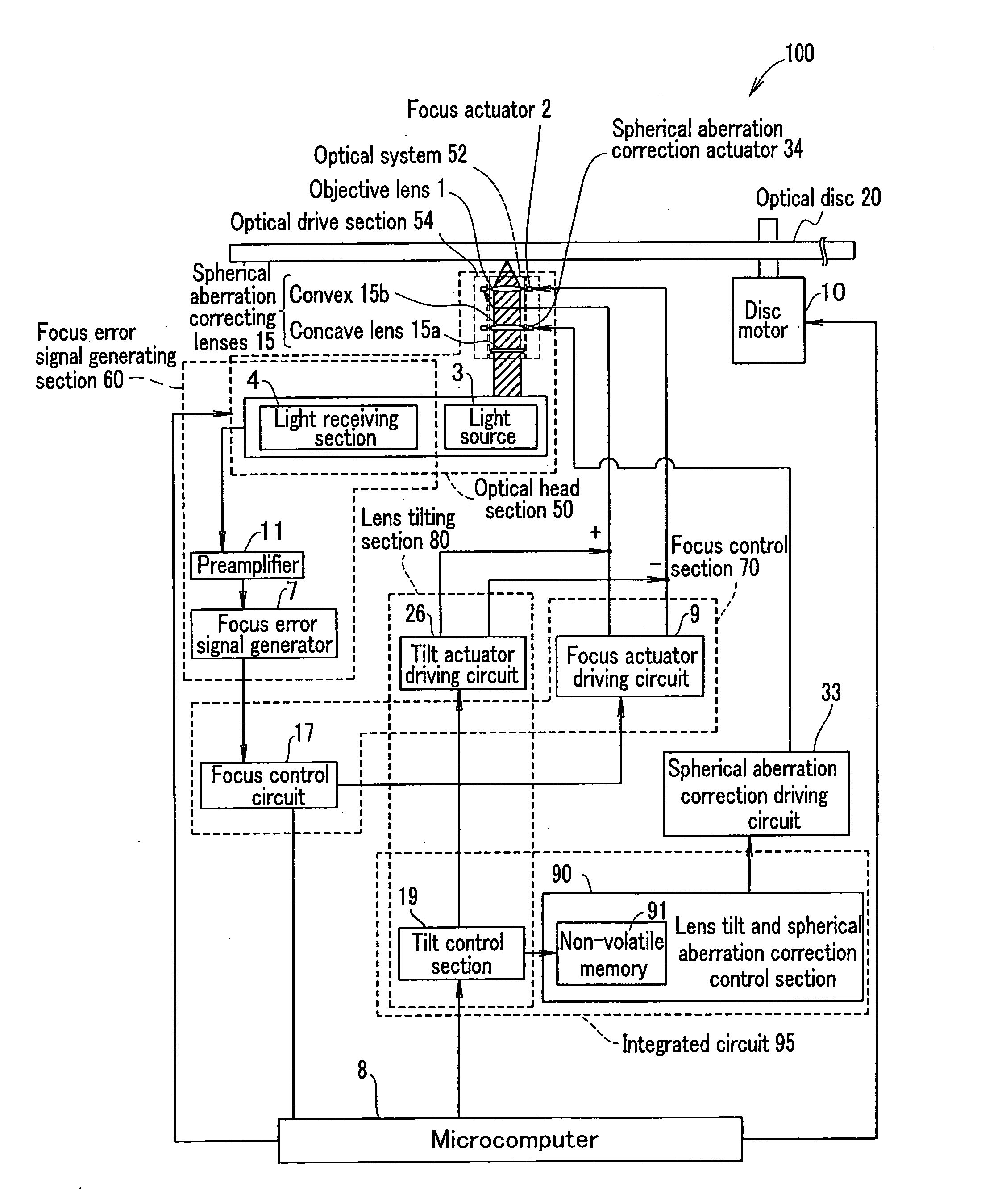
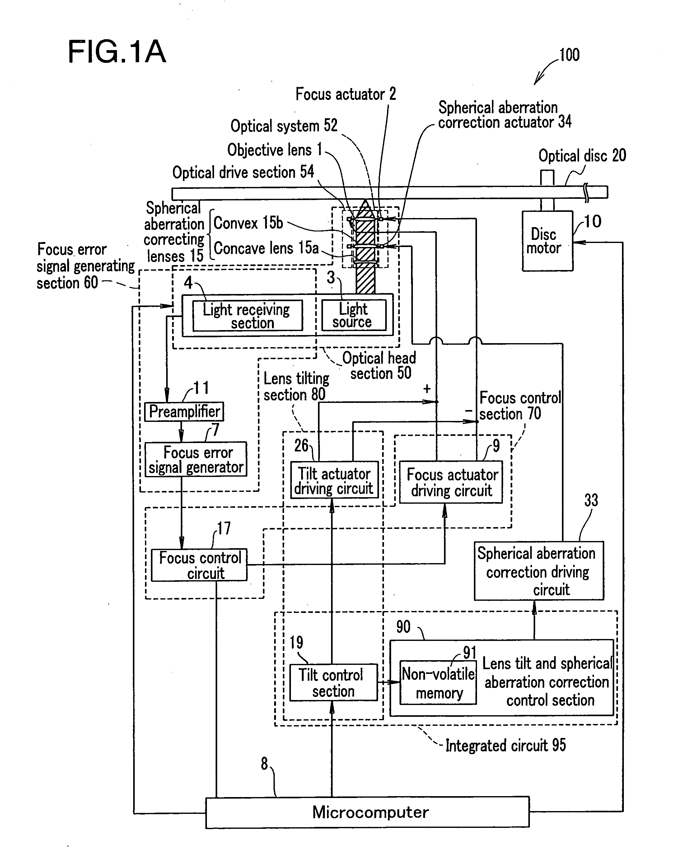
FIG. 1A is a block diagram showing an optical disc apparatus 100 according to Embodiment 1 of the present invention.

The optical disc apparatus 100 records information to an optical disc 20 and / or reproduces information from the optical disc 20.

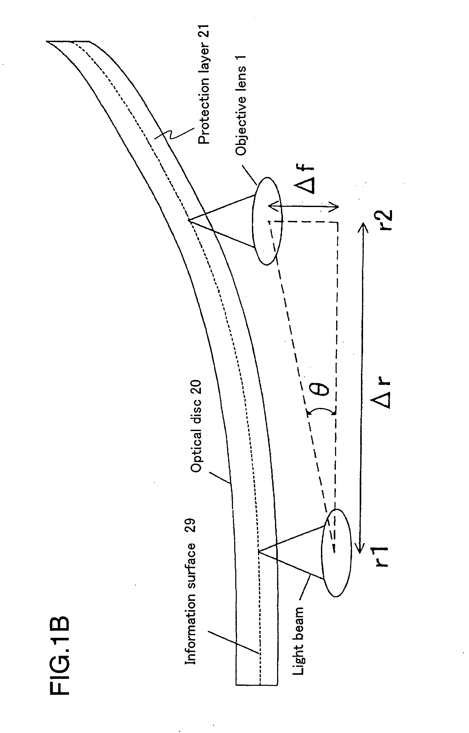
The optical disc 20 comprises an information surface for recording information (not shown in FIG. 1A) and a protection layer (not shown in FIG. 1A) for protecting the information surface, the protection layer being provided on the information surface. In addition, tracks are provided on the information surface of the optical disc 20.

The optical disc apparatus 100 comprises: a disc motor 10 for rotating the optical disc 20 loaded thereon at a predetermined rpm; an optical head section 50; a focus error signal generating section 60 for generating a focus error signal; a focus control section 70 for controlling the focus of a light beam based on the focus error signal; a lens tilting section 80 for tilting an objective lens 1 depending on t...

embodiment 2

FIG. 6A is a block diagram showing an optical disc apparatus 200 according to Embodiment 2 of the present invention.

The optical disc apparatus 200 is different from the optical disc 100 of FIG. 1A in that the optical disc apparatus 200 further comprises a lens tilt-spherical aberration correction amount determining section 92 for determining an amount of correction of spherical aberration depending on the tilt of the objective lens 1 in accordance with a signal output from the preamplifier 11.

Parts of the optical disc apparatus 200 having the same functions as those of corresponding parts of the optical disc apparatus 100 are referred to by the same reference characters and the description thereof is omitted for the sake of brevity.

The lens tilt-spherical aberration correction control section 90 comprises a non-volatile memory 91, in which a correspondence between a tilt of the objective lens 1 and an amount of spherical aberration correction is written in advance.

The lens t...


PUM


Abstract

An optical disc apparatus is provided, which comprises a lens tilting section for tilting an objective lens to correct coma aberration occurring in a light beam spot focused on an information surface of an optical disc, a spherical aberration correcting section for correcting spherical aberration occurring in a light beam spot focused on the information surface, and a lens tilt-spherical aberration correction control section for controlling the spherical aberration correcting section to change an amount of spherical aberration correction performed by the spherical aberration correcting section depending on a tilt of the objective lens tilted by the lens tilting section.

Description

BACKGROUND OF THE INVENTION 1. Field of the Invention The present invention relates to an optical disc apparatus and a spherical aberration correction controlling apparatus. 2. Description of the Related Art Recently, optical discs, such as DVD-ROM, DVD-RAM, DVD−RW, DVD−R, DVD+RW, DVD+R, and the like, have been developed as high density / large capacity recording media. To date an optical lens having a numerical aperture (NA) of 0.6 has been used as an objective lens of an optical disc apparatus for recording information onto the above-described optical discs and / or reproducing information from those optical discs. In order to obtain an optical disc having a higher density / larger capacity (e.g., a Blue-ray Disc (BD), etc.), the use of a blue-violet laser and an optical lens having an NA of 0.8 or more has been studied. For the above-described optical discs, a multi-layer structure having two or more recording layers (information surfaces) has been studied. Hereinafter, lens til...

Claims


Application Information

Patent Timeline
IPC IPC(8): G02B13/24G11B7/00G11B7/09G11B7/095G11B7/13G11B7/135
CPCG11B7/0943G11B7/0956G11B7/131G11B2007/13727G11B7/1378G11B7/1381G11B7/13927G11B7/1374
Inventor KUZE, YUUICHIWATANABE, KATSUYAKONDO, KENJIYAMADA, SHIN-ICHI
Owner PANASONIC CORP
Why Eureka
Try Eureka