Gamut mapping between multiple boundary regions

a color image data and boundary region technology, applied in the field of color image data gamut mapping, can solve the problems of inability to achieve optimal tonal mapping, difficult to accurately depict the true gamut of the device, and inability to accurately reproduce the color imag

Active Publication Date: 2005-03-03
CANON KK +1
View PDF13 Cites 42 Cited by
  • Summary
  • Abstract
  • Description
  • Claims
  • Application Information

AI Technical Summary

Benefits of technology

[0017] In this manner, the gamut mapping of the present invention utilizes supplied descriptions of color boundary regions of a source and of a destination media so that a source image can be appropriately gamut mapped to an output medium on an output device, such as a printer, for a proper reproduction of the sour

Problems solved by technology

Gamut mapping becomes more difficult when using an unrendered picture from an input device such as a camera or a video camera.
This present problems when gamut mapping the unrendered picture from the input device, such as a camera, to an output medium in an output device, such as a printer, primarily because it is not known at the time of gamut mapping where the whitest-white points and the blackest-black points of the unrendered picture fall on the input medium with respect to the white point and the black point of the input medium.
Thus, there is substantial headroom and footroom in the encoding scheme that go unused in a typical representation of a device gamut, thereby resulting in an incomplete depiction of the true gamut of the device.
Unfortunately for the graphic arts industry, when it is desired to reproduce an unrendered image from a particular video device on an output device such as a printer, optimal tonal mapping is difficult, if not impossible.
In addition to the above-mentioned problems with gamut mapping during the reproduction of unrendered photographic and video images onto an output device with a different gamut boundary, photographic and video devices produce gray colors which do not necessarily fall on the neutral axis of the color appearance model used to depict the color gamut of the photograph and/or video device.
This representation of gray colors in the

Method used


Image

  • Gamut mapping between multiple boundary regions
  • Gamut mapping between multiple boundary regions
  • Gamut mapping between multiple boundary regions

Examples


Embodiment Construction

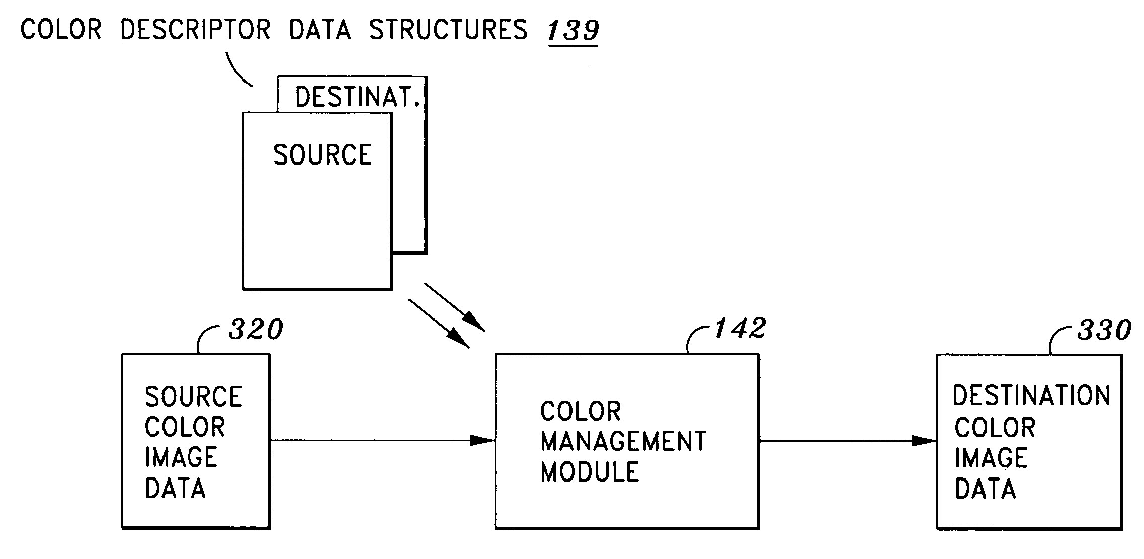
[0041] The present invention provides a color descriptor data structure for a color device which contains a reference boundary descriptor representing reference colors of the color device, a plausible boundary descriptor representing plausible colors of the color device which include a whitest-white color and a blackest-black color, and a neutral color descriptor representing neutral colors of the color device which extend in range from the whitest-white color to the blackest-black color. According to the present invention, the color descriptor data structure can be used to appropriately gamut map an unrendered image, such as a photographic or video image, to an output medium on an output device, such as a printer, so that reproduction of the range of colors from the whitest-white to the blackest-black on the output medium is made possible.

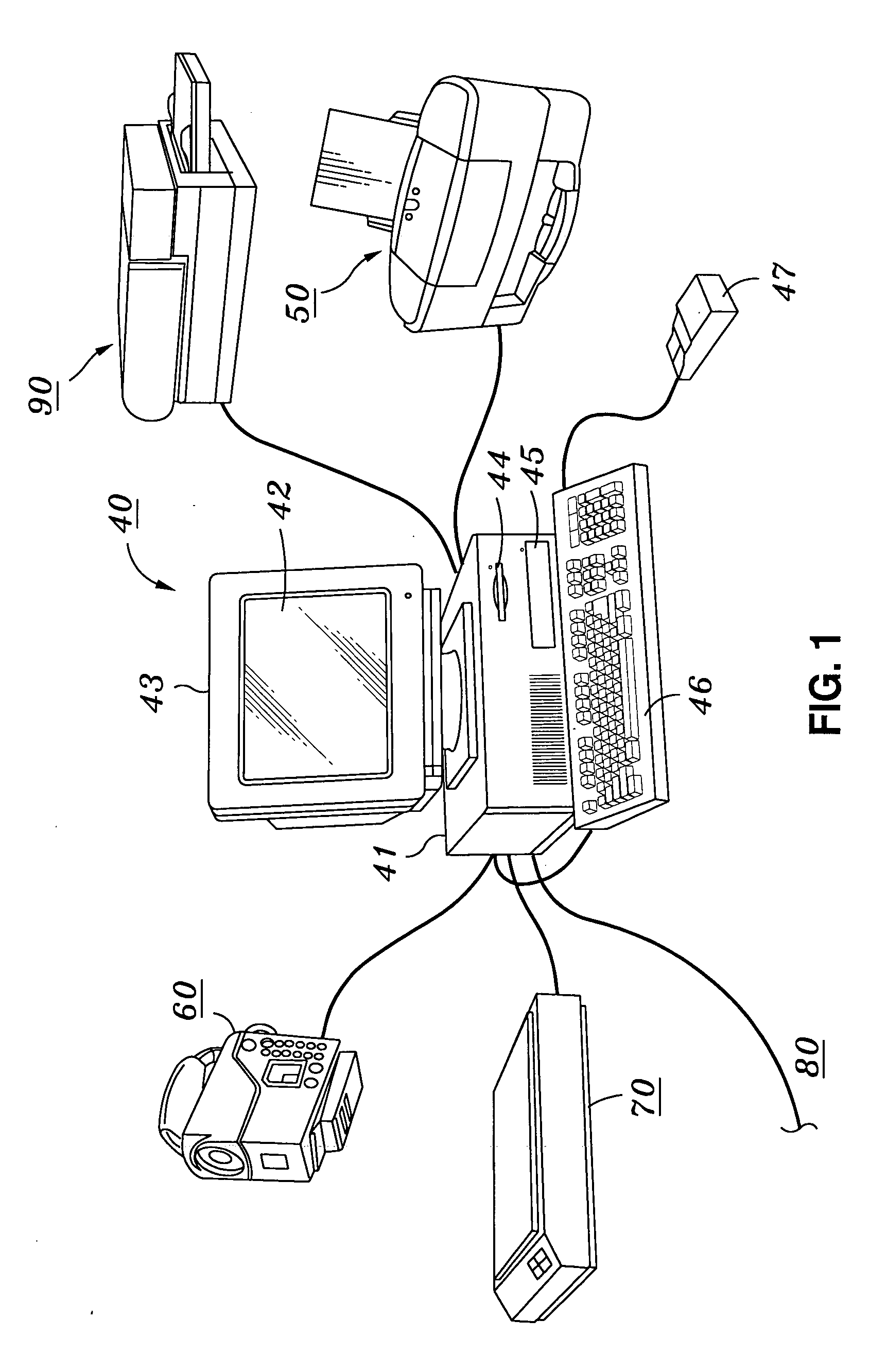
[0042] Turning to FIG. 1, a computing environment is shown in which the present invention may be implemented. FIG. 1 depicts a representative co...


PUM


Abstract

Mapping color image data from a source color gamut to a destination color gamut, wherein the mapping includes identifying source color boundary regions in the source color gamut based on descriptor data provided in a source color descriptor data structure, and determining a position of each identified source color boundary region, identifying destination color boundary regions in the destination color gamut based on descriptor data provided in a destination color descriptor data structure, and determining a position of each identified destination color boundary region, and mapping the color image data from the identified source color boundary regions to the identified destination color boundary regions based on a correspondence between the determined positions of the identified source color boundary regions and the determined positions of the identified destination color boundary regions.

Description

INCORPORATION BY REFERENCE [0001] U.S. patent application No. ______, entitled “Color Descriptor Data Structure”, filed concurrently with this application, is incorporated herein by reference. BACKGROUND OF THE INVENTION [0002] 1. Field of the Invention [0003] The present invention relates to the gamut mapping of color image data from within a source color gamut to within a destination color gamut. In particular, the present invention maps the color image data to within the destination color gamut by identifying source color boundary regions in the source color gamut based on descriptor data provided in a source color descriptor data structure, identifying destination color boundary regions in the destination color gamut based on descriptor data provided in a destination color descriptor data structure, and mapping the color image data from the identified source color boundary regions to be within the corresponding identified destination color boundary regions based on the relative ...

Claims


Application Information

Patent Timeline
IPC IPC(8): G06FG06K9/00H04N1/60
CPCH04N1/6058
Inventor NEWMAN, TODD D.HAIKIN, JOHN S.HENLEY, SHARON A.
Owner CANON KK
Why Eureka
Try Eureka