Method and assembly for rotating a cutting insert during a turning operation and inserts used therein

a technology of rotating cutting inserts and turning operations, applied in the direction of cutting inserts, shaping cutters, manufacturing tools, etc., can solve the problems of the same spinning inserts failing in an equally dramatic fashion, and the type of spinning inserts showing extraordinarily long tool life at remarkable speeds

Active Publication Date: 2005-03-03
KENNAMETAL INC
View PDF20 Cites 57 Cited by
  • Summary
  • Abstract
  • Description
  • Claims
  • Application Information

AI Technical Summary

Problems solved by technology

This type of spinning insert may exhibit extraordinarily long tool life at remarkable speeds.
However, this same spinning insert may fail in an equally dr

Method used


Image

  • Method and assembly for rotating a cutting insert during a turning operation and inserts used therein
  • Method and assembly for rotating a cutting insert during a turning operation and inserts used therein
  • Method and assembly for rotating a cutting insert during a turning operation and inserts used therein

Examples


Embodiment Construction

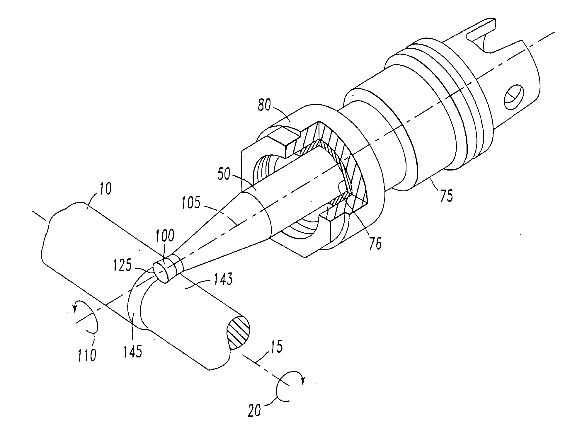
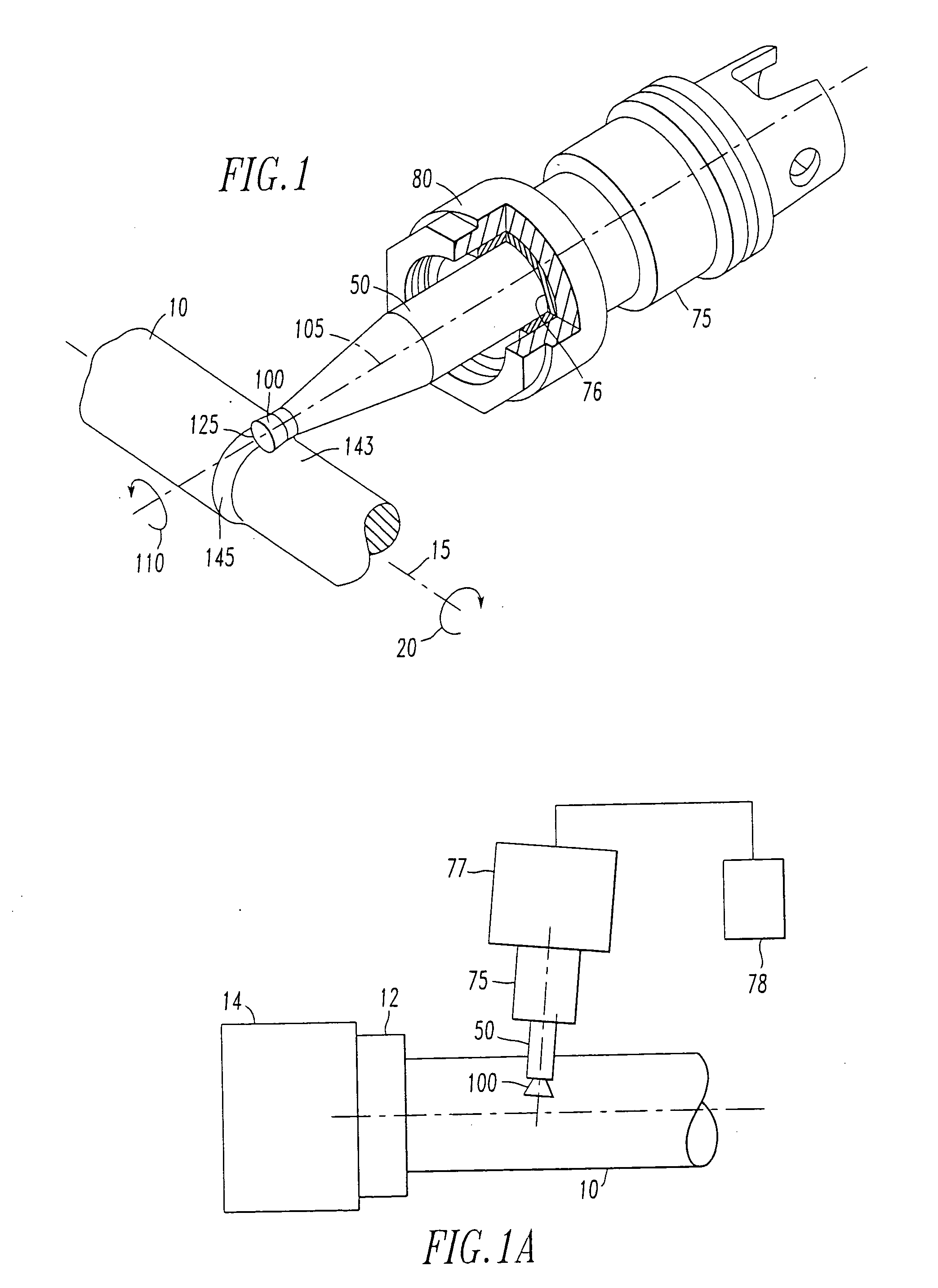
[0030]FIG. 1 illustrates a workpiece 10 rotating about a centerline 15 in a direction indicated by arrow 20 wherein, for example, the workpiece 10 is mounted upon a lathe. A toolholder 50 has mounted thereupon a cutting insert 100. The cutting insert 100 has a central axis 105. The insert 100 is secured to the toolholder 50 in a non-rotatable fashion such that rotation of the toolholder 50 is translated directly to rotation of the cutting insert 100. As one example, the insert 100 and the toolholder 50 may rotate in the direction illustrated by arrow 110.

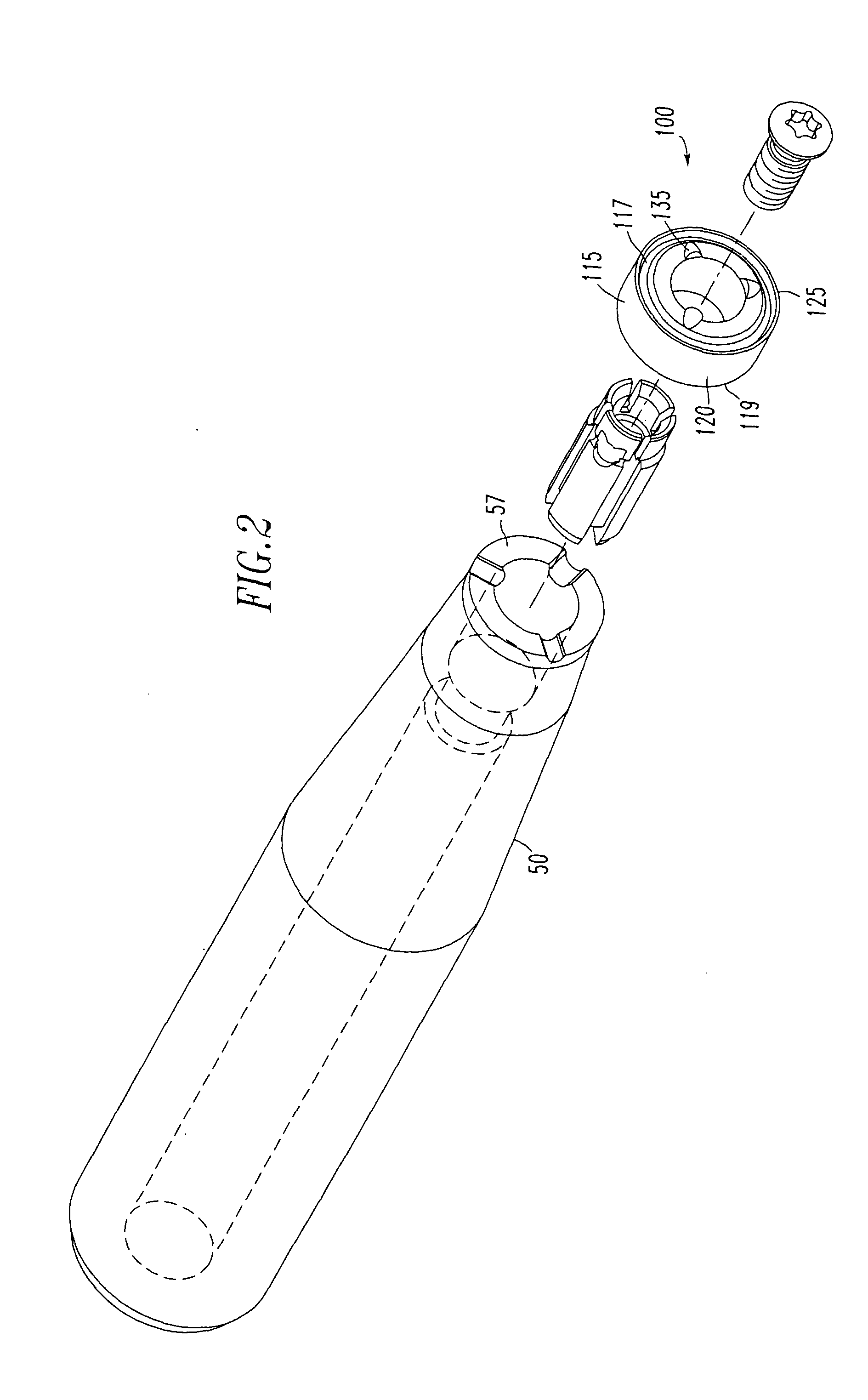
[0031] An assembly is comprised, in part, of the cutting insert 100 with its central axis 105 extending therethrough. The insert, as illustrated in FIGS. 2-4, has a body 115 with a top surface 117 and a bottom surface 119 with at least one side 120 therebetween. A cutting edge 125 is defined at the intersection of the at least one side 120 and the top surface 117. The cutting insert 100 is mounted upon the toolholder 50 and the too...


PUM

PropertyMeasurementUnit
Lengthaaaaaaaaaa
Angleaaaaaaaaaa
Diameteraaaaaaaaaa

Abstract

A cutting insert rotated about its axis may be utilized during a metalworking operation and applied against the rotating workpiece to enhance tool performance. A method, including an assembly with a rotatable insert mounted to a toolholder may be utilized to achieve this result.

Description

BACKGROUND OF THE INVENTION [0001] 1. Field of the Invention [0002] The invention is directed to metalworking operations and, more particularly, to a method and assembly for rotating a cutting insert about the insert central axis during a metalworking operation. The subject invention is also directed to the cutting insert itself, the assembly with a toolholder and such an insert, and the operation of the assembly. [0003] 2. Description of Related Art [0004] During a metalworking operation, such as a turning operation, where a stationary cutting insert is urged against a rotating workpiece, the insert cutting edge acting upon the workpiece is heated by the workpiece until the operation is complete or until the cutting edge begins to break down through a failure mechanism, such as crater wear or plastic deformation. To avoid these modes of failure, and to permit more efficient operation of the cutting insert, in the past, circular cutting inserts have been mounted upon toolholders, su...

Claims


Application Information

Patent Timeline
IPC IPC(8): B23B1/00B23B27/10B23B27/12B23B27/16B23B31/40B23G1/02B23Q11/10
CPCB23B1/00Y10T407/235B23B27/12B23B27/1603B23B31/4006B23B2200/0438B23B2200/0461B23B2200/081B23B2200/161B23B2200/204B23B2260/042B23B2265/16B23G1/02Y10T409/305656Y10T82/10Y10T407/23Y10T407/14Y10T407/2286Y10T409/309408Y10T409/303808Y10T279/16Y10T407/194Y10T82/2529Y10T409/303976B23B27/10B23B27/16B23Q11/10
Inventor HYATT, GREGORY A.ANDRAS, LINN R.MASSA, TED R.
Owner KENNAMETAL INC
Why Eureka
Try Eureka