Clamp and method of making same

a technology of clamping mechanism and clamping mechanism, which is applied in the field of clamping, can solve the problems of not being suited to tubular structures, unable to accurately limit the amount of force exerted by clamping structures, and being difficult to use, so as to prevent over-tightening, prevent cracking of glass barrels, and be convenient to use.

Inactive Publication Date: 2005-03-03
GEN PROBE INC
View PDF28 Cites 18 Cited by
  • Summary
  • Abstract
  • Description
  • Claims
  • Application Information

AI Technical Summary

Benefits of technology

The structure of the present invention provides a number of non-limiting advantages. For example, in syringe pump applications the clamp is constructed and arranged to provide sufficient holding torque to resist rotation of the syringe while preventing over-tightening of the clamp on the syringe during clamp installation, thereby preventing cracking of the glass barrels. Additionally, the present invention provides a novel design which allows obvious orientation for installation, making it efficient and easy to use.
According to one aspect of the present invention, a clamp includes a hoop section and first and second actuating elements. The hoop section forms a portion of a generally circular closed loop with first and second opposed ends defining a gap therebetween. The first and second actuating elements, each having first and second ends, are coupled to the first and second ends of the hoop section, respectively. The first and second actuating elements extend along opposite sides of the hoop section with the second ends of the actuating elements being in an opposed, spaced-apart relation with respect to each other. The actuating elements are constructed and arranged to cause the hoop section to expand when the second ends of the first and second actuating elements are moved toward each other, thereby increasing the size of the gap.
According to another aspect of the present invention, a clamp includes hoop means for holding a generally cylindrical object and which defines a cavity, anti-slipping means disposed on an interior surface of the hoop means for resisting slippage between the hoop means and the cylindrical object, and actuating means for causing the hoop means to open to allow the cylindrical object to be placed within the cavity.
According to another aspect of the invention, a syringe pump assembly includes a mechanized syringe and an anti-rotation clamp secured to the syringe and constructed and arranged to prevent rotation of the syringe by contacting a structure adjacent to the syringe. The mechanized syringe includes a barrel, a plunger disposed within the barrel for reciprocating movement therein, and a motor operatively coupled to the plunger for effecting mechanized movement of the plunger. The anti-rotation clamp comprises a hoop section and first and second actuating elements. The hoop section forms a portion of a closed loop and has first and second ends defining a gap therebetween. The hoop section is constructed and arranged to generate a clamping force when placed on the syringe to secure the clamp to the syringe. The first and second actuating elements each have first and second ends. The first ends of the first and second actuating elements are coupled to the first and second ends, respectively, of said hoop section, and the first and second actuating elements extend along opposite sides of the hoop section. The second ends of the actuating elements are in opposed, spaced-apart relation with respect to each other. The actuating elements are constructed and arranged to cause the hoop section to expand when the second ends of the first and second actuating elements are moved toward each other, thereby increasing the size of the gap to permit the hoop section to be placed on the syringe.
According to another aspect of the invention, an assembly comprises a generally cylindrical element and a clamp secured to the cylindrical element. The cylindrical element includes solid elements as well as a hollow (i.e., tubular) elements. The clamp comprises a hoop section which forms a portion of a closed loop and which has first and second ends defining a gap therebetween. The hoop section is constructed and arranged to generate a clamping force when placed on the cylindrical element to secure the clamp to the cylindrical element. The clamp further comprises first and second actuating elements, each having first and second ends. The first ends of the first and second actuating elements are coupled to the first and second ends, respectively, of the hoop section, and the first and second actuating elements extend along opposite sides of the hoop section with the second ends of the actuating elements being in opposed, spaced-apart relation with respect to each other. The actuating elements are constructed and arranged to cause the hoop section to expand when the second ends of the first and second actuating elements are moved toward each other, thereby increasing the size of the gap to permit the hoop section to be placed on the cylindrical element.

Problems solved by technology

While the two clamps illustrated in FIGS. 1 and 2 may be able to hold certain tubular structures, these clamps lack a mechanism for accurately limiting the amount of force they exert on such structures.
While these prior art clamps may be suited for strong tubular structures made from materials which can sustain relatively large clamping forces without buckling or breaking, such as steel or thick plastic, they are not suited for tubular structures, such as those made of brittle materials such as glass, or pliable materials such as aluminum, which are delicate and can be easily cracked, broken or buckled if subjected to large clamping forces.
Such pumps include syringes having tubular portions—known as barrels—that are constructed of ground glass, which is a very delicate material vulnerable to cracking when subjected to point contact forces.
However, without a force limiting mechanism, the clamps can cause the delicate glass barrels of the syringes to crack, resulting in leaks and wasted material.

Method used


Image

  • Clamp and method of making same
  • Clamp and method of making same
  • Clamp and method of making same

Examples


Embodiment Construction

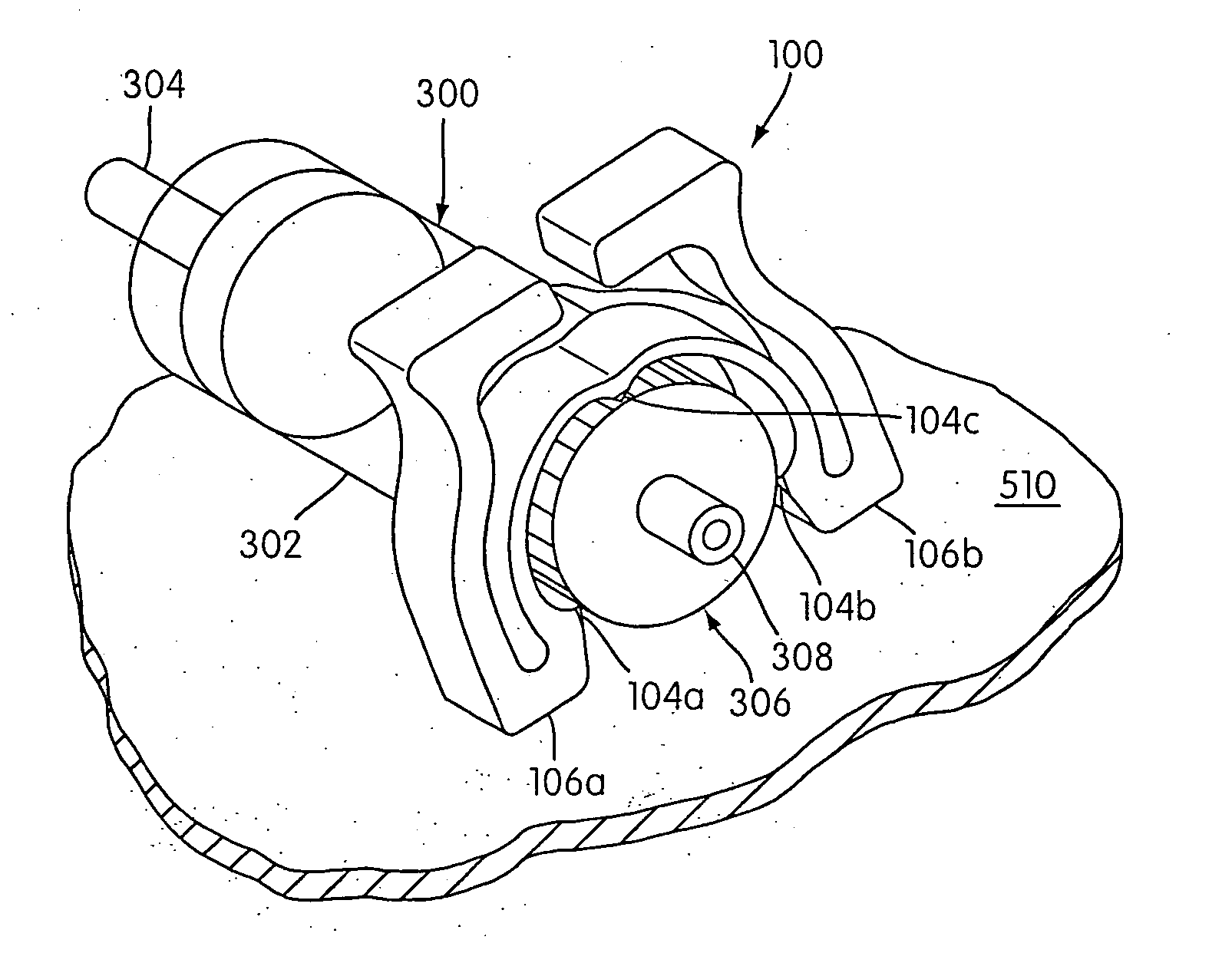
FIGS. 3A-3D illustrate a clamp according to a preferred embodiment of the present invention generally indicated by reference number 100. Referring to FIG. 3A, the clamp 100 has a clamp body that is generally symmetrical about a planar section B-B and has two opposing sections 100a and 100b, which mirror one another with reference to plane B-B. Each section 100a, 100b includes an arcuate section 102a, 102b, which together form a hoop section 102 that defines a generally circular cavity for receiving an object (e.g., cylindrical object 200—which may be a solid cylindrical element or a hollow (i.e., tubular) cylindrical element—shown in FIG. 3A in phantom) to be clamped. Hoop section 102 may also include anti-slipping elements formed along an interior surface 103 thereof which are constructed and arranged to prevent slippage of the clamp 100 with respect to an object being clamped. For example, the anti-slipping elements may comprise a number of circumferentially-spaced radial projecti...


PUM

PropertyMeasurementUnit
angleaaaaaaaaaa
angleaaaaaaaaaa
angleaaaaaaaaaa

Abstract

A clamp includes a hoop section and actuating elements. The hoop section forms a cavity for holding a tubular object. The hoop section has first and second ends. First and second actuating elements are respectively coupled with the first and second ends of the hoop section. Squeezing the ends of the actuating members together causes the hoop section to expand to facilitate installation of the clamp onto an object to be clamped and removal of the clamp from the object. Thus, the clamping force generated by the clamp is limited by the restoring forces inherent in the shape, sized, and material of the hoop section when the actuating members are released. The actuating members include expansion limiting extensions which contact each other after a prescribed amount of expansion of the hoop section to thereby prevent further expansion, and possible yielding, of the hoop section. The clamp can be employed as an anti-rotation device secured to a syringe of a syringe pump.

Description

BACKGROUND OF THE INVENTION 1. Field of the Invention This invention generally pertains to a clamp with a built-in load limitation mechanism. More particularly, the present invention is directed to a clamp which relies on the elastic force inherent in its shape and the material of which it is made to thereby exert a uniform and controlled force on a structure held thereby. 2. Description of the Related Art Known clamp devices suitable for holding tubes or hoses are described below and are depicted in FIGS. 1 and 2. FIG. 1 shows a prior art clamp 10 comprising a curved resilient portion 12. Extending from the curved resilient portion 12 is a first post 14 with an unthreaded hole 22 located at the free end of first post 14. Also extending from an opposite end of the curved resilient portion 12 is a second post 16, and extending off of the end of the second post 16 is a projection 18. The projection 18 has a threaded hole 24 coaxially aligned with and directly opposed to the unthre...

Claims


Application Information

Patent Timeline
Patent Type & Authority Applications(United States)
IPC IPC(8): A61M5/14A61M5/142A61M5/145F16B2/06F16B2/20F16B2/22F16B5/06F16L3/12
CPCA61M5/1418A61M5/14216A61M5/1452A61M5/1456F16B2/065Y10T24/44872F16B2/22F16B5/0685F16L3/1203Y10T24/44538F16B2/20
Inventor KENNEDY, MARK R.KNIGHT, BYRON J.
Owner GEN PROBE INC
Why Eureka
Try Eureka