Carriage type conveyor

a conveyor and carriage technology, applied in the direction of transportation and packaging, rope railways, roads, etc., can solve the problems of difficult conveyor implementation and increase the cost of equipment, and achieve the effect of simple structur

Active Publication Date: 2005-03-10
DAIFUKU CO LTD
View PDF4 Cites 4 Cited by
  • Summary
  • Abstract
  • Description
  • Claims
  • Application Information

AI Technical Summary

Benefits of technology

[0006] Thus, while the carriage is passing across the passage, at least two of the six guided members, which are the main guided members, front auxiliary guided members and rear auxiliary guided members, engage with at least one of the three guide rails, which are the main guide rail, front auxiliary guide rail and rear auxiliary guide rail, on at least one side of the passage. Accordingly, while the carriage is passing across the passage, one or more of the guide rails guide the carriage always at two points spaced from each other in the running direction. This makes it possible to move the carriage very linearly across the passage, where there is no guide rail for guiding the carriage. Consequently, the carriage is prevented from stopping at the passage in case it could not engage with the main guide rail on the downstream side of the passage.
[0007] This conveyor is simpler and less costly in comparison with a case where large carriage guides might be used additionally on both sides of the passage to hold the carriage on both sides of the carriage so that the carriage could pass only linearly across the passage. There may be a case where the first track section includes a turning path either just upstream or just downstream of the passage. Particularly in this case, it would be necessary that the carriage guides could be opened and closed so as not to interfere with the ends of the carriage, which shift outward of the turning path while the carriage is running along this path. This would greatly raise the cost of equipment and need switching control of the carriage guides, making it difficult to implement the conveyor. The present invention makes it possible to achieve its object by implementing the conveyor simply and easily without the foregoing inconveniences.
[0009] The first track section may include at least one turning path. While the carriage is running along the turning path, both ends of the carriage shift temporarily to the outer side of this path, which is away from the center of curvature of the path, and subsequently return to their original positions. In this case, it is preferable that at least whichever of the pair of front auxiliary guided members and the pair of rear auxiliary guided members is positioned inside the turning path with respect to the main guide rail, i.e., on that side of this rail to which the turning path forward of the carriage in the running direction curves is positioned higher than the rail. The higher guided members avoid colliding with the main guide rail when they shift laterally with respect to the running direction while the carriage is running along the turning path. This makes it possible to also apply the present invention to a track layout including a turning path.
[0010] The turning path may be either just downstream or just upstream of the passage. In this case, while the carriage is running along the turning path, the higher auxiliary guided members, which are positioned inside this path, avoid colliding with the main guide rail. Depending on the direction in which the turning path curves, however, when both ends of the carriage shift laterally while it is running along this path, the front auxiliary guided members may collide with the rear auxiliary guide rail, which is upstream of the passage, or the rear auxiliary guided members may collide with the front auxiliary guide rail, which is downstream of the passage. Accordingly, in addition to the arrangement where the auxiliary guided members at least inside the turning path with respect to the main guide rail are positioned higher than this rail, the pair of front auxiliary guided members may differ in height from the pair of rear auxiliary guided members. Whichever of the pair of front auxiliary guided members and the pair of rear auxiliary guided members is higher may be positioned higher than the auxiliary guide rail for engaging with the lower pair of auxiliary guided members. This prevents the front auxiliary guided members from colliding laterally with the rear auxiliary guide rail, which is upstream of the passage, or the rear auxiliary guided members from colliding with the front auxiliary guide rail, which is downstream of the passage.
[0011] Each of the main and auxiliary guide rails may consist of a pair of vertical plates. Each of the main and auxiliary guided members may be a vertical pin supported rotatably on a vertical axis for engaging with the inner sides of the vertical plates. The vertical plates and pins are simple in structure and cheap.

Problems solved by technology

This would greatly raise the cost of equipment and need switching control of the carriage guides, making it difficult to implement the conveyor.

Method used


Image

  • Carriage type conveyor
  • Carriage type conveyor
  • Carriage type conveyor

Examples


Embodiment Construction

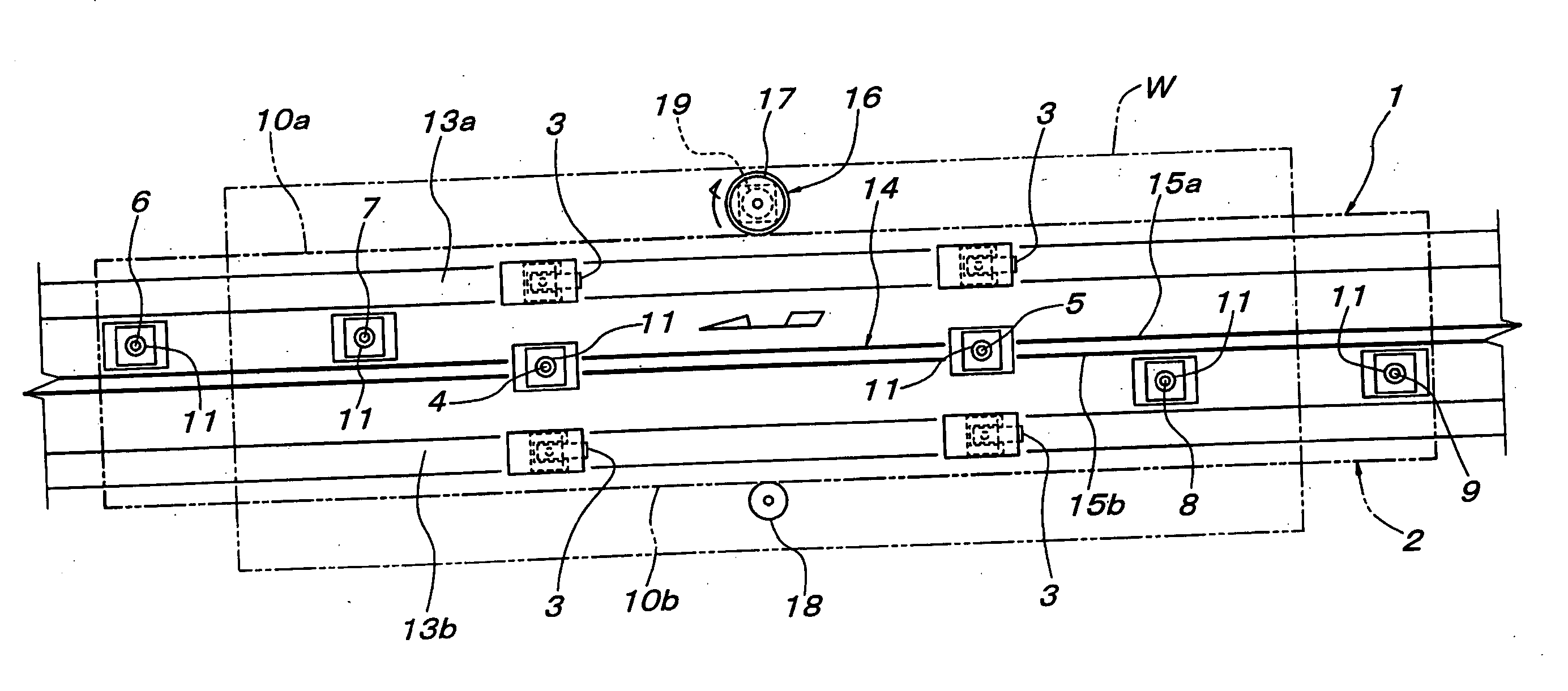
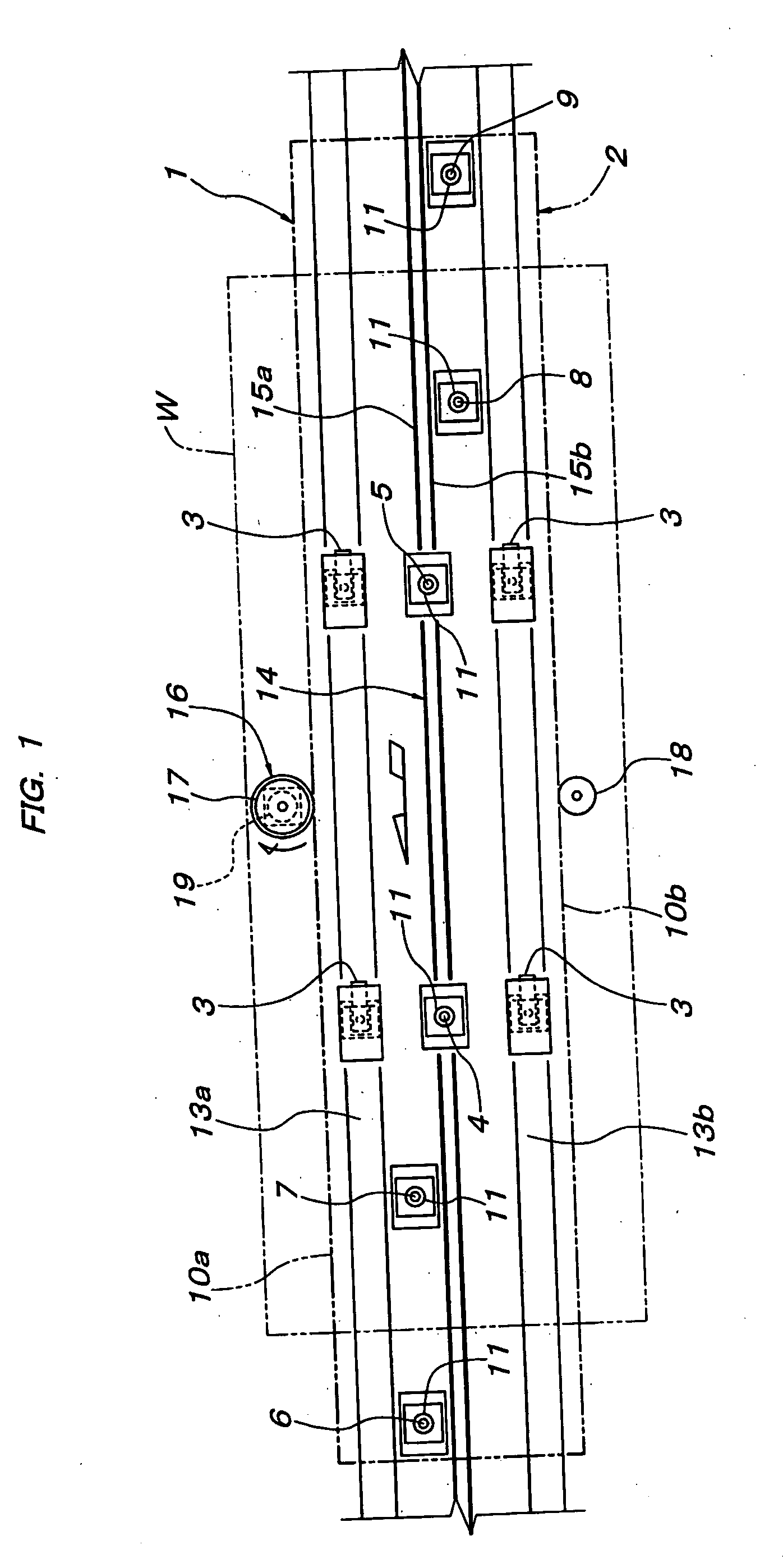
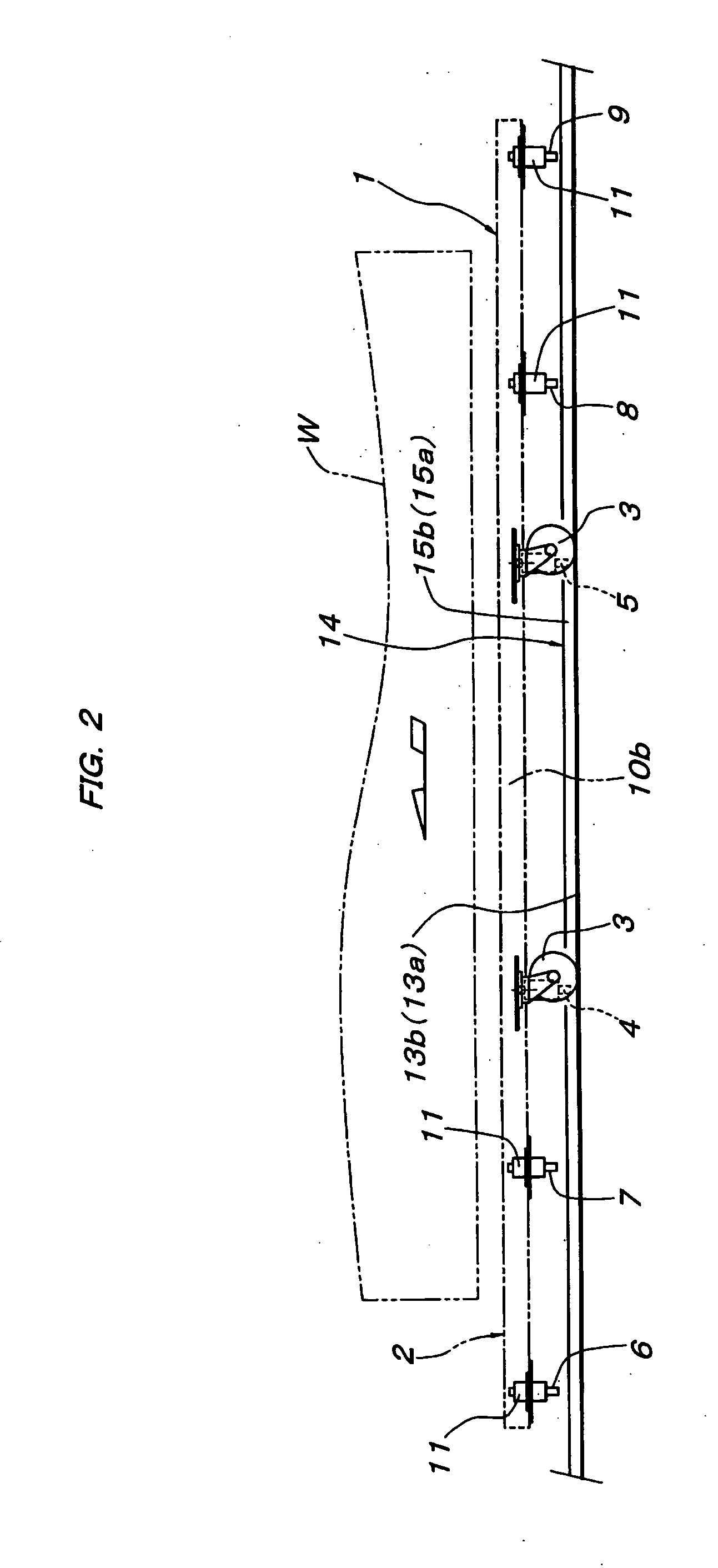
[0023] With reference to FIGS. 1-5, a friction-drive carriage type conveyor embodying the present invention includes a carriage 1, which runs in a running direction along a horizontal closed-loop track on a floor. The carriage 1 includes a long integral deck 2 for supporting a car body or another work W. The deck 2 has no horizontal joint between both its ends.

[0024] The deck 2 has a pair of frictional surfaces 10a and 10b formed on its right and left sides, respectively, in the running direction. The frictional surfaces 10a and 10b are the right and left side surfaces of the deck 2 itself. Alternatively, the frictional surfaces 10a and 10b might be side surfaces of one or more longitudinal members fixed to the deck 2.

[0025] The bottom of the deck 2 is fitted with a pair of front casters 3 and a pair of rear casters 3. The casters 3 are positioned on both sides of the center line of the deck 2.

[0026] The bottom of the deck 2 is also fitted with a front main guided member 4, a rea...


PUM


Abstract

A friction-drive carriage type conveyor includes a carriage 1 for running in a running direction along a horizontal track including a first track section and a second track section, which crosses a passage 26. Friction drivers 29 and 30 are fitted on both sides of the passage 26 to drive the carriage 1 across it. A main guide rail 14 lies along the whole length of the first track section. A rear auxiliary guide rail 31 lies along the first track section and is upstream of the passage 26. A front auxiliary guide rail 32 lies along the first track section and is downward of the passage 26. The carriage 1 is fitted with a pair of main guided members 4 and 5 for engaging with the main guide rail 14, a pair of front auxiliary guided members 6 and 7 for engaging with the front auxiliary guide rail 32, and a pair of rear auxiliary guided members 8 and 9 for engaging with the rear auxiliary guide rail 31. The main guided members 4 and 5 are spaced from each other in the running direction. The front auxiliary guided members 6 and 7 are forward of the main guided members 4 and 5 and spaced from each other in the running direction. The rear auxiliary guided members 8 and 9 are backward of the main guided members 4 and 5 and spaced from each other in the running direction. The auxiliary guided members 6-9 are positioned on either side of the main guide rail 14. While the carriage 1 is passing across the passage 26, at least two of the guided members 4-9 engage with the associated guide rail or rails 14, 31 and / or 32 on one or both sides of this passage. This ensures that the carriage 1 passes linearly across the passage 26.

Description

FIELD OF THE INVENTION [0001] The present invention relates to a friction-drive carriage type conveyor with a relatively long integral carriage, which has no horizontal joint over its whole length. PRIOR ART [0002] For example, Japanese Unexamined Patent Publication No. 2001-48006 discloses a friction-drive carriage type conveyor including a carriage for running along a horizontal track. The carriage is fitted with casters for rolling on the track. A guide rail lies along the track. The carriage is also fitted with a pair of guided members for engaging with the guide rail. The guided members are positioned near the center of the carriage and spaced from each other in the running direction in which the carriage runs. The carriage has a frictional surface extending in the running direction. A friction driver can contact with the frictional surface to drive the carriage along the track. [0003] In such a friction-drive carriage type conveyor, if the horizontal track crosses a passage, t...

Claims


Application Information

Patent Timeline
Patent Type & Authority Applications(United States)
IPC IPC(8): B61B13/12B61B10/04B65G35/06
CPCB65G35/06B61B13/127B61B13/12
Inventor NAKAMURA, TAKUSHIOOE, MASAHIRO
Owner DAIFUKU CO LTD
Why Eureka
Try Eureka