
Apparatus for processing substrate in chamber and maintenance method therefor

a technology for a substrate and an apparatus, which is applied in the direction of coatings, chemical vapor deposition coatings, metallic material coating processes, etc., can solve the problems of imposing a burden on the operator, requiring a lot of working hours, and sometimes breaking the substra

Inactive Publication Date: 2005-03-10
DAINIPPON SCREEN MTG CO LTD
View PDF24 Cites 13 Cited by
  • Summary
  • Abstract
  • Description
  • Claims
  • Application Information

AI Technical Summary

Benefits of technology

[0011] In the present invention, it is possible to perform maintenance for the inside of the chamber body without removing the holding part.
[0012] Preferably, the lower surface of the holding part is moved by the moving mechanism up to a level higher than the upper surface of the edge of the opening by 100 mm or more. It thereby becomes possible for an operator to perform maintenance with his hands put into the chamber body.

Problems solved by technology

Especially, in a thermal processing apparatus for executing a thermal processing with flash lamps, a substrate is sometimes broken due to rapid thermal expansion of its surface into pieces to be scattered in the chamber since a flash of the flash lamps raises the surface temperature of the substrate in an extremely short time.
Further, after the maintenance is finished, it is also necessary to equip the components which have been taken out from the inside of the chamber again through accurate positioning and execute operations for adjustment such as checking on whether the apparatus should normally operate or not, and this imposes an burden on an operator and requires a lot of working hours.
In recent, with upsizing of a substrate, components in the chamber (especially, the holding part for holding the substrate) are upsized, and therefore maintenances needing detachment and attachment of these components require further labor and time.

Method used


Image

  • Apparatus for processing substrate in chamber and maintenance method therefor
  • Apparatus for processing substrate in chamber and maintenance method therefor
  • Apparatus for processing substrate in chamber and maintenance method therefor

Examples


Embodiment Construction

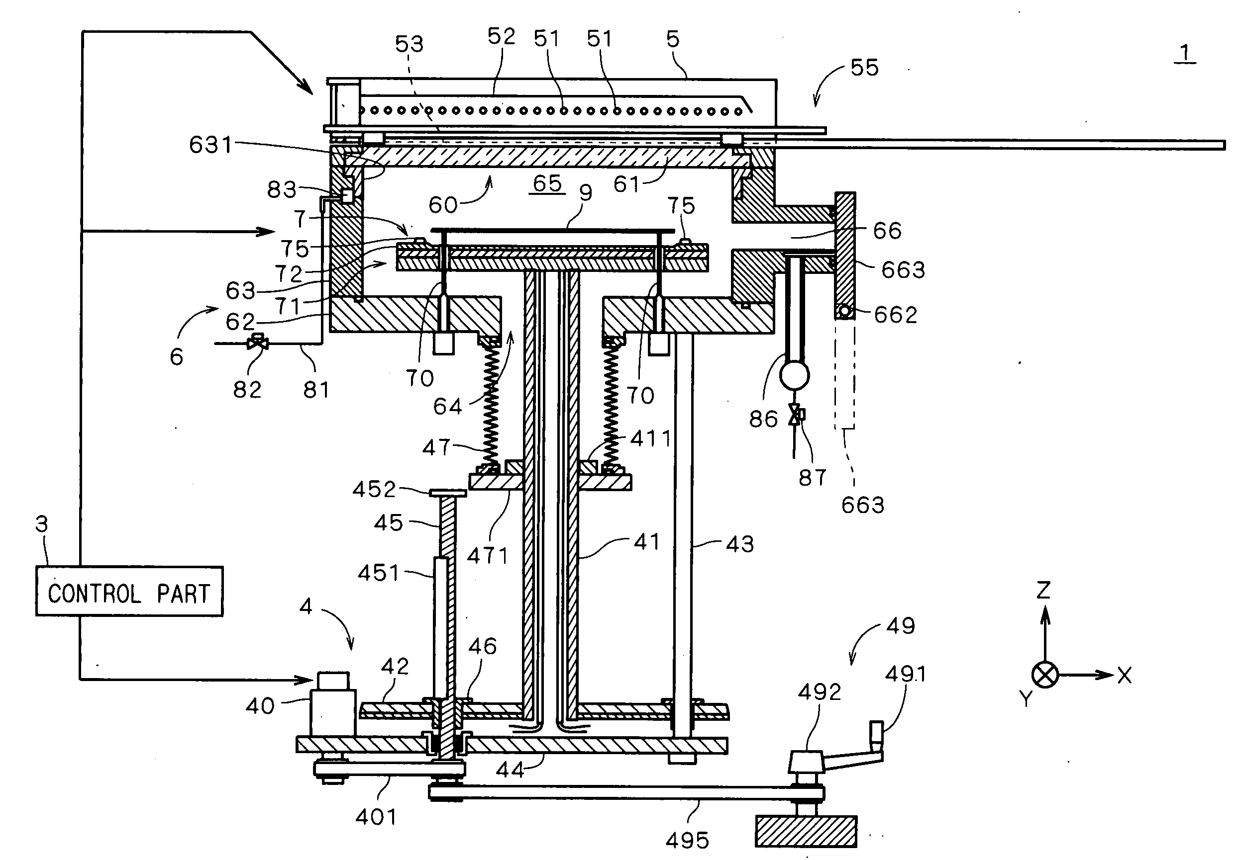
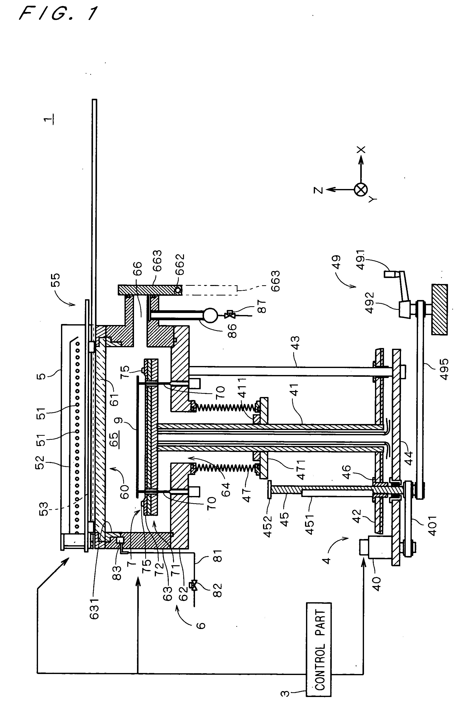
[0027]FIG. 1 is a view showing a construction of a thermal processing apparatus 1 in accordance with one preferred embodiment of the present invention. The thermal processing apparatus 1 is an apparatus for performing a processing accompanied with heating through irradiating a semiconductor substrate 9 (hereinafter, referred to as “substrate 9”) with light.

[0028] The thermal processing apparatus 1 comprises a chamber side part 63 having a substantially-cylindrical inner wall and a chamber bottom 62 covering a lower portion of the chamber side part 63, which constitute a chamber body 6 forming a space (hereinafter, referred to as “chamber”) 65 for thermally processing the substrate 9 and comprising an opening (hereinafter, referred to as “upper opening”) 60 in its upper portion.

[0029] The thermal processing apparatus 1 further comprises a transparent plate 61 which is a closing member attached to the upper opening 60 for closing the upper opening 60, a substantially disk-shaped hol...


PUM

PropertyMeasurementUnit
temperatureaaaaaaaaaa

Abstract

A thermal processing apparatus (1) comprises a chamber body (6) having an upper opening (60), a transparent plate attached to the upper opening (60) to close the upper opening (60), a holding part (7) for holding and heating a substrate in the inside of the chamber body (6) and a holding-part moving mechanism (4) for moving the holding part (7) up and down. In performing maintenance of the thermal processing apparatus (1), the transparent plate is removed from the chamber body (6) and then the holding part (7) is moved by the holding-part moving mechanism (4) up to a position where a lower surface (77) of the holding part (7) is higher than an upper surface (69) of an edge of the upper opening (60). This allows maintenance for the inside of the chamber body (6) from a gap (601) between the holding part (7) and the chamber body (6) without removing the holding part (7) from the chamber body (6).

Description

BACKGROUND OF THE INVENTION [0001] 1. Field of the Invention [0002] The present invention relates to an apparatus for processing a substrate in a chamber and a maintenance method for the apparatus. [0003] 2. Description of the Background Art [0004] Conventionally, in a process of manufacturing semiconductor substrates, glass substrates for display devices or the like (hereinafter, referred to simply as “substrates”), various processings are performed for the substrates in chambers. For example, in a process of forming an oxide film or the like, a processing through heating is generally performed for a substrate in a chamber and a rapid thermal process (hereinafter, referred to as “RTP”) is used as a method of thermal processing. In the RTP, by heating the substrate in the chamber with halogen lamps or the like to raise the temperature thereof up to a predetermined temperature in a short time, it is possible to perform processings which have been hard to execute by a conventional lon...

Claims


Application Information

Patent Timeline
Patent Type & Authority Applications(United States)
IPC IPC(8): C23C16/44C23C16/48H01L21/31H01L21/26H01L21/304
CPCC23C16/481C23C16/4401
Inventor SATO, TORUWATANABE, JUN
Owner DAINIPPON SCREEN MTG CO LTD
Learn More