Device and method for injection molding

Active Publication Date: 2021-09-02
FOBOHA GERMANY
View PDF0 Cites 0 Cited by
  • Summary
  • Abstract
  • Description
  • Claims
  • Application Information

AI Technical Summary

Benefits of technology

The invention provides a rotating device for an injection molding machine that is easy and quick to assemble and disassemble for maintenance purposes. This reduces maintenance time by up to 60% compared to prior art. The device includes a sleeve and a column with grooves for exchanging media between them. The heavy and bulky injection molds don't need to be removed from the machine, making the process easier and more efficient. Overall, the invention improves the performance and handling of the injection molding device.

Problems solved by technology

In the devices known from the prior art the maintenance time is a critical aspect as they require a complete disassembly which usually is very time consuming.
One significant disadvantage is that the heavy and bulky injection molds consisting of the first and second outer mold halves, as well as the center mold part must be at least partially removed from the injection molding machine in which they are installed.

Method used


Image

  • Device and method for injection molding
  • Device and method for injection molding
  • Device and method for injection molding

Examples


Embodiment Construction

[0030]Reference will now be made in detail to certain embodiments, examples of which are illustrated in the accompanying drawings, in which some, but not all features are shown. Indeed, embodiments disclosed herein may be embodied in many different forms and should not be construed as limited to the embodiments set forth herein; rather, these embodiments are provided so that this disclosure will satisfy applicable legal requirements. Whenever possible, like reference numbers will be used to refer to like components or parts.

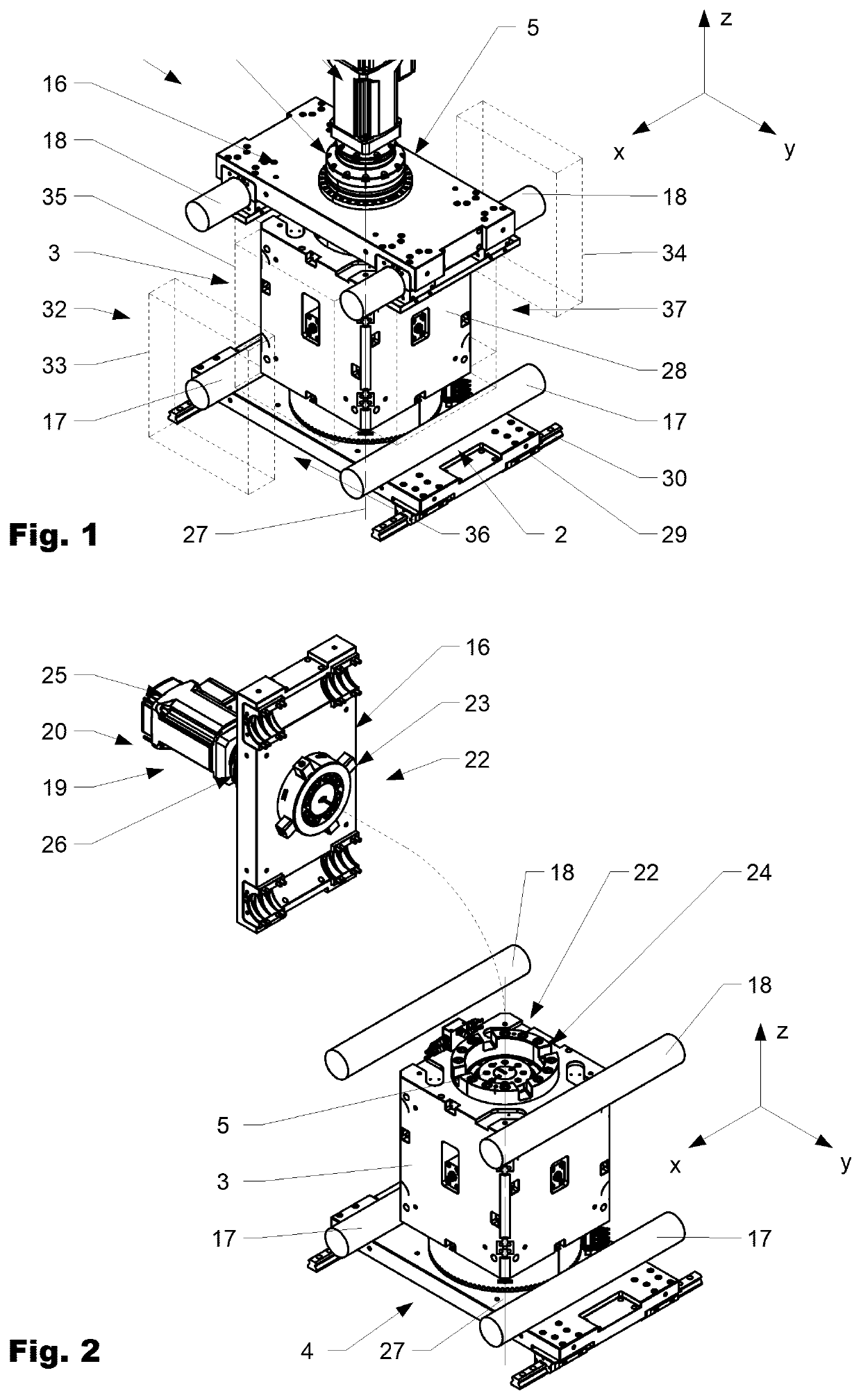
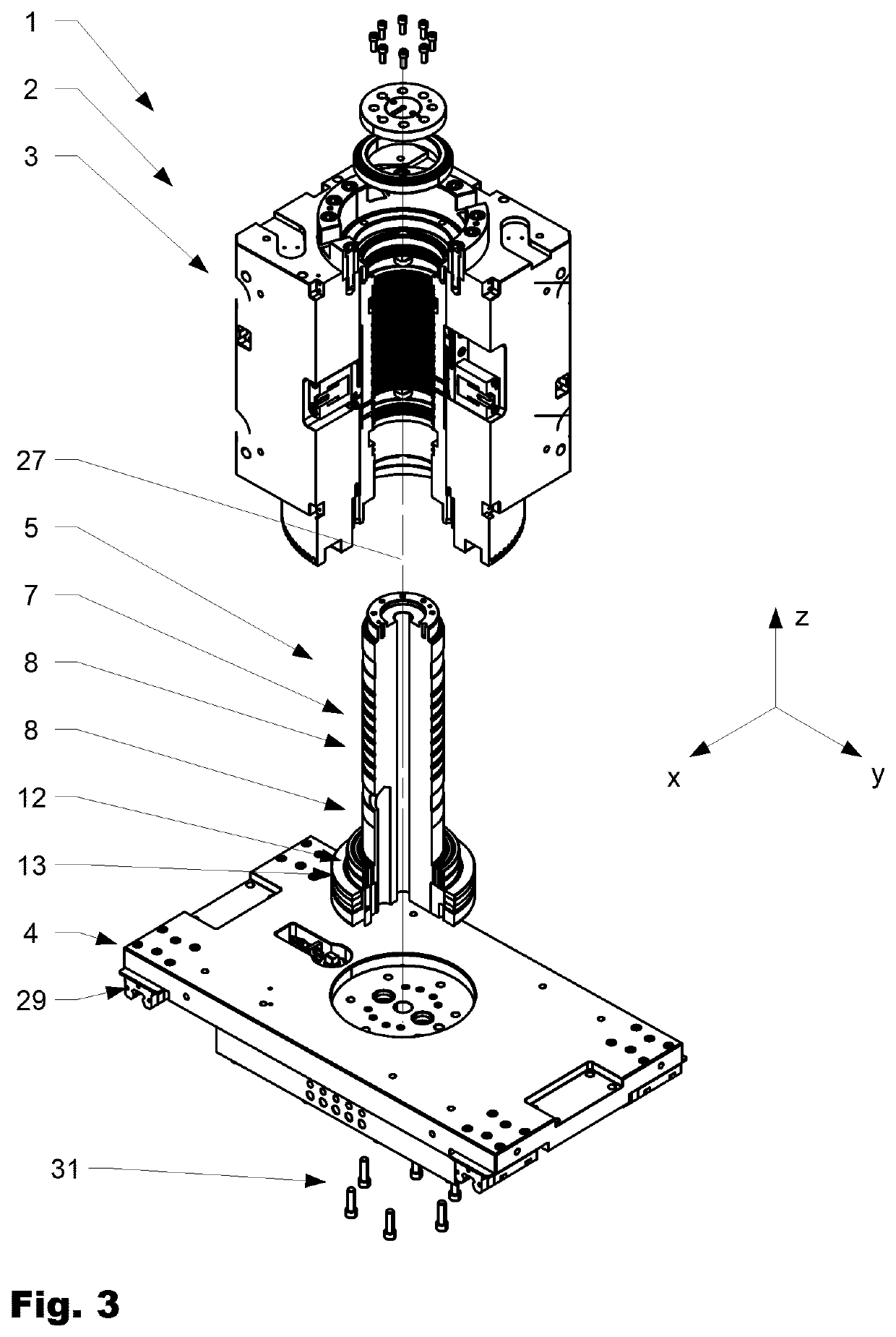
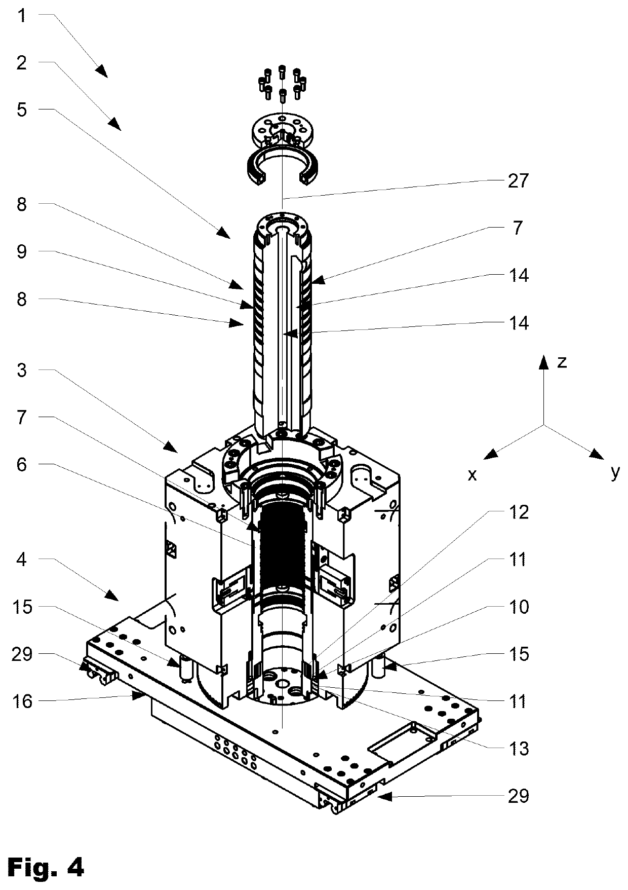
[0031]FIG. 1 shows a variation of an injection molding device 1 according to the invention in a perspective manner from above. FIG. 2 shows the injection molding device 1 according to FIG. 1 in a partially dismantled position. FIG. 3 shows the injection molding device 1 in an exploded view. FIG. 4 shows the injection molding device 1 in another partially dismantled position. FIG. 5 shows a further variation of the injection molding device 1 in a perspective, part...


PUM

PropertyMeasurementUnit
Diameteraaaaaaaaaa

Abstract

An injection molding device (1) includes a center part (3) and a rotating device (2) for rotating the center part (3) in the injection molding device (1). The rotating device (2) includes a base (4) supported with respect to an injection molding machine. A thereto attached column (5) extends in an axial direction (z) above the base (4). A sleeve (6) coaxially surrounds the column (5) and is at least partially arranged in the center part (3). The sleeve (6) rotates with the center part (3) around the column (5). The column (5) is arranged removable with respect to the center part (3).

Description

BACKGROUND OF THE INVENTIONField of the Invention[0001]The present invention lies in the field of devices and methods for injection molding, namely of plastic products.Discussion of Related Art[0002]From the prior art devices for injection molding of plastic products are known which comprise a first outer mold half and a thereto along tie bars of an injection molding machine in a first direction relative to the first outer mold half displaceable second outer mold half. Between the first and the second outer mold half a center part is arranged rotatable around a center axis extending in vertical direction. The center part comprises at least two but more often four side faces which are arranged in pairs parallel to each other and which each carry an inner mold half. The inner mold halves in a closed position of the injection molding device interact with the first and the second outer mold halves in a first and in a second separation plane forming cavities suitable to receive melted pl...

Claims


Application Information

Patent Timeline
IPC IPC(8): B29C45/04B29C45/16B29C45/73B29C45/26
CPCB29C45/045B29C45/1628B29C2045/2689B29C45/2681B29C2045/0458B29C45/7312
Inventor ARMBRUSTER, RAINER
Owner FOBOHA GERMANY
Why Eureka
Try Eureka