Control housing and method of manufacturing same

a technology of control housing and control body, which is applied in the direction of contact surface shape/structure, broadcast transmission system, etc., can solve the problems of inability to sterilize contaminants that may have entered the pendant itself, wear of printed insignia, and small crevices or gaps around the pendant's buttons, etc., to achieve the effect of convenient cleaning

Inactive Publication Date: 2005-03-10
NEECO TRON
View PDF16 Cites 18 Cited by
  • Summary
  • Abstract
  • Description
  • Claims
  • Application Information

AI Technical Summary

Benefits of technology

[0013] In all embodiments, the membrane housing and backing are preferably formed from a rigid plastic, and the membrane is formed from a soft, pliable plastic. The membrane is molded, in situ, on the cover body, and is applied via a process which will allow the membrane to fuse with the body plastic. By fusing the membrane to the cover body, a seal is formed between the membrane and the cover body which will substantially prevent gases, liquids, and / or solids (i.e., particulate matter) from entering the cavity which housing the control board. Further, the cover surface of the pendant is smooth. That is, it has no sharp corners which will trap particulate matter. Hence, the pendant is easily cleaned.

Problems solved by technology

However, over time, the printed insignia wears off.
Further, current manufacturing procedures for the pendant housings result in small crevices or gaps around the pendant's buttons through which contaminants (i.e., liquids, gases, and even small solids or particulate matter) can pass and come into contact with the control board.
Thus, although the pendant itself can be wiped, for example, with alcohol, to clean, disinfect, and sterilize the surface of the pendant, any contaminants that may have entered the pendant itself cannot be sterilized.
When contaminants enter the pendant housing, they can affect the operation of the device being controlled if they reach the control board within the housing.
Further, in a hospital setting, such contaminants can lead to cross-contamination.
The current production methods for producing hospital bed controllers tend to result in controllers which are fairly thick.

Method used


Image

  • Control housing and method of manufacturing same
  • Control housing and method of manufacturing same
  • Control housing and method of manufacturing same

Examples


first embodiment

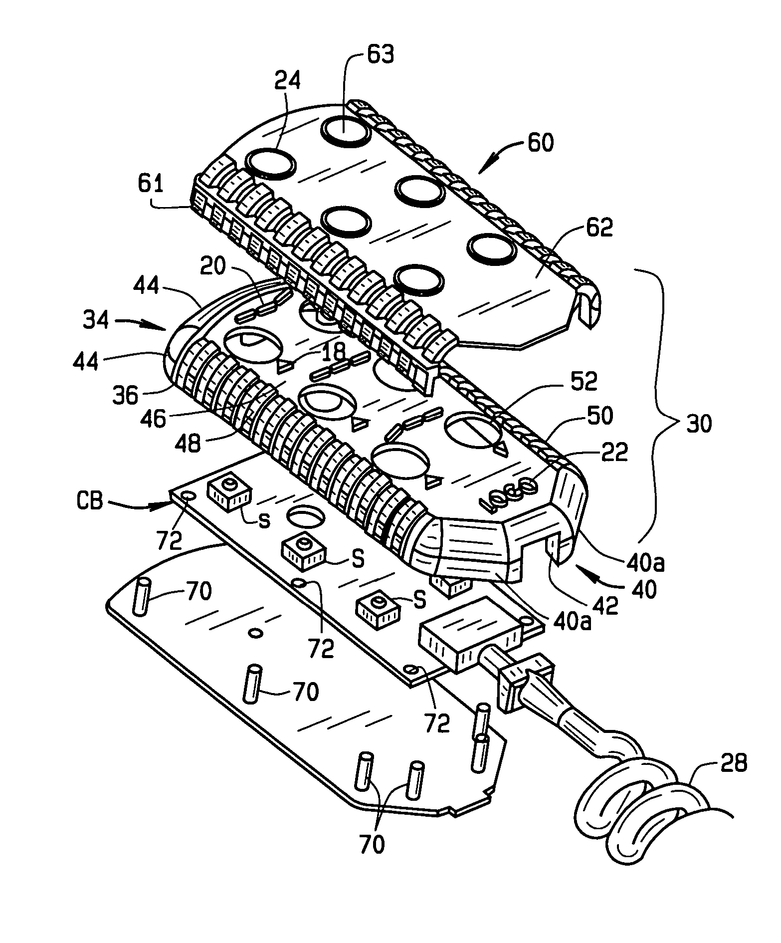
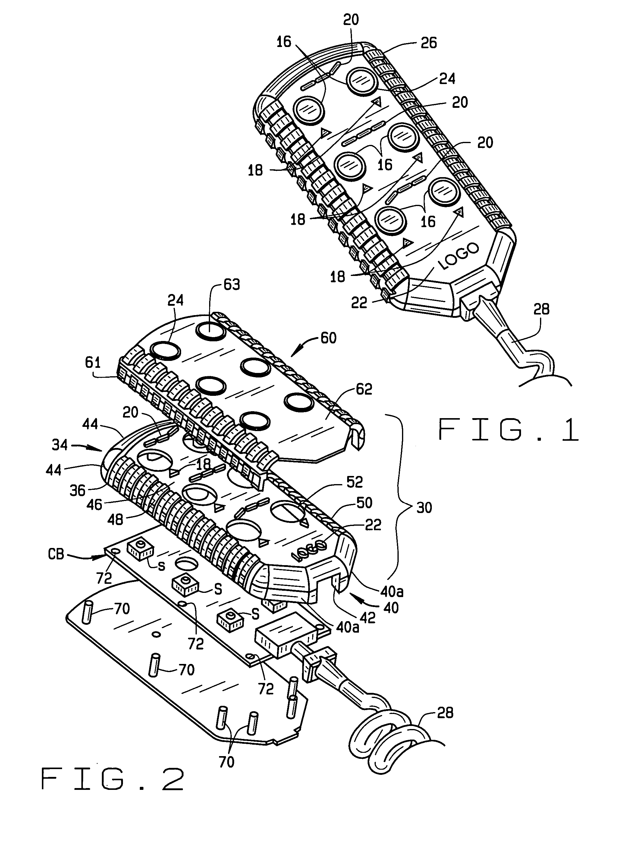
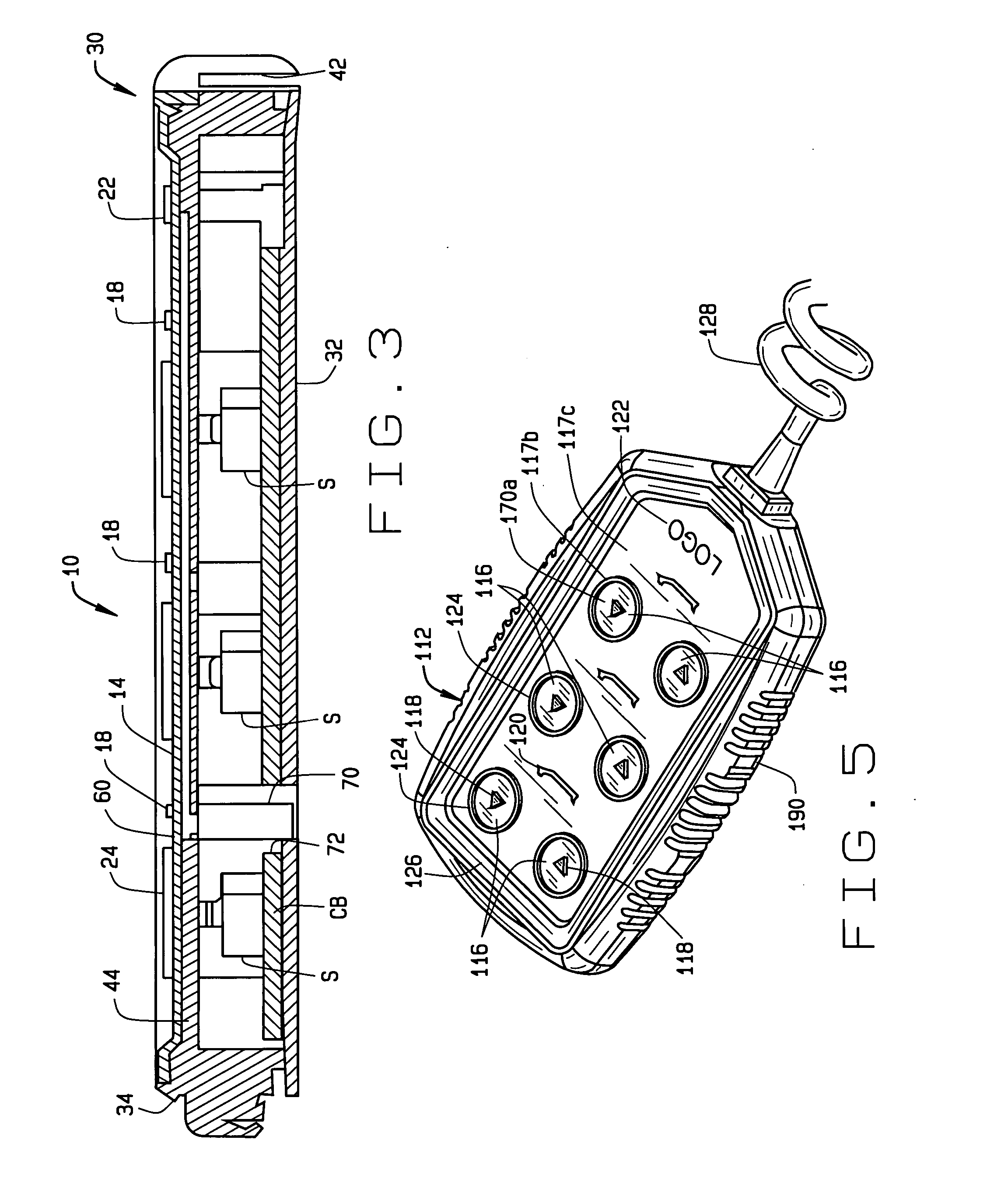
[0033] the pendant is shown in FIGS. 1-3. The pendant 10 includes a housing 12 having a front face 14, a back, and side walls which define a cavity C (FIG. 3) in which a control board CB (FIG. 2) is mounted. The pendant includes a series of buttons 16 on the front face 14. First instructional insignia 18 in the form of up and down arrows is provided near each button 16. A second instructional insignia 20 also is provided near each set of buttons to indicate the function of the button. Illustratively, in FIG. 1, the first instructional insignia 18 is in the shape of up and down arrows and is positioned centered and below its respective button. The second instructional insignia 20 is positioned above and between its respective buttons. Thus, in the pendant shown in FIG. 1, the top set of buttons control the position or angle of the head of the bed; the middle set of buttons control the bed height; and the bottom set of buttons control the position or angle of the foot or end of the be...

second embodiment

[0043] the pendant is shown in FIGS. 5-7. The pendant 110 includes a housing 112 having a front face 114, a back, and side walls which define a cavity in which a control board CB (FIG. 6) is mounted. The pendant includes a series of buttons 116 on the front face 114. First instructional insignia 118 in the form of up and down arrows is provided on each button 116 and second instructional insignia 120 is provided adjacent each set of buttons to indicate the function of the button. Additionally, an identifying insignia 122 can be provided which includes a logo, trademark, or the like which identifies the pendant. The buttons 116 can each include a raised rim 124 around the circumference of the button. Such a rim makes it easier, for example, to locate the buttons in dim light and for physically impaired patients to locate the buttons and reduces the possibility of accidental activation of the unit, for example, when the unit is dropped or when something is dropped on the unit. Additio...

third embodiment

[0060] the pendant is shown in FIGS. 10-12. The pendant 310 is generally similar to the pendant 110, however, its button layer does not include a channel to receive an insignia insert. In this embodiment, as explained below, the two operating insignia are the same color. However, the identifying insignia can be a different color.

[0061] The pendant 310 comprises a housing 312 which includes a backing or bottom 314 and a cover 316. The cover 316, in turn, comprises a body 318, a button insert or plate 320, and a casing 322. The housing 312 holds the control board CB to which the optional cord 324 is connected. The cord, as is common, includes a strain relief 326 at the junction between the cord and the housing and a head 327 from which a connector extends to mates with a receptacle on the board CB, as is known. The head 327 includes a hole 328. When the pendant is assembled, the head hole 328 is passed over an alignment pin, as will be described below.

[0062] The control board CB incl...


PUM

PropertyMeasurementUnit
flexibleaaaaaaaaaa
heightaaaaaaaaaa
coloraaaaaaaaaa

Abstract

A control housing is provided which encases a control board. The housing has a cover and a backing which are fixed together to secure the control board within the housing. The control board includes a plurality of switches, and the housing includes a plurality of corresponding buttons to activate the switches. The cover includes a cover surface having at least one button hole in register with the control board switch; operating insignia integrally formed on the cover surface adjacent the button hole; and a membrane which closes said button hole to form a button surface. The insignia is exposed through the membrane to be exposed and visible. The membrane is fused to the cover, thereby providing a housing which is sealed to substantially prevent gases, liquids or solids from entering the housing.

Description

CROSS-REFERENCE TO RELATED APPLICATIONS [0001] Not Applicable. STATEMENT REGARDING FEDERALLY SPONSORED RESEARCH OR DEVELOPMENT [0002] Not Applicable. BACKGROUND OF THE INVENTION [0003] This invention relates to control housings (commonly referred to as pendants) which house control boards used to control equipment, such as hospital beds or other electronic equipment device requiring remote control, and to a method for producing the housings to mold instructional or operating insignia directly onto the housing. [0004] Hand held controls or pendants are commonly used in the medical field to control various types of medical equipment. One common place such pendants are used is to control the position of hospital beds. As is known, the position of a hospital bed can be changed to alter (1) the height of the bed; (2) the angle of the head of the bed; and (3) the angle of the foot of the bed. Typically, a control unit is mounted to the bed itself for use by hospital staff. However, to let...

Claims


Application Information

Patent Timeline
Patent Type & Authority Applications(United States)
IPC IPC(8): H01H9/02H04H20/82H01H13/70
CPCH01H9/0242Y10T29/49904H01H13/70H01H2217/018H01H2217/024H01H2223/002H01H2223/003H01H2223/054H01H2229/046H01H2229/048H01H2237/004H01H2239/03Y10T29/4998Y10T29/49885H01H9/025
Inventor MAHONEY, MICHAEL R.NIBERT, L. NICHOLASLINHOFF, DAVID M.
Owner NEECO TRON
Why Eureka
Try Eureka