Tape cartridge soft load system

a technology of soft load and cartridge, which is applied in the field of soft load system of tape cartridge, can solve the problems of prone to failure, complicated operation, and high manufacturing cost of soft load mechanisms

Inactive Publication Date: 2005-03-10
QUANTUM CORP
View PDF7 Cites 10 Cited by
  • Summary
  • Abstract
  • Description
  • Claims
  • Application Information

AI Technical Summary

Benefits of technology

[0005] In accordance with embodiments of the present invention, a tape drive system is provided. The tape drive system comprises: a stationary base; at least one guide projection mounted to the stationary base; and a receiver for receiving a tape cartridge and transporting the tape cartridge from an ejected position to a loaded position, the receiver comprising at least one guide slot mating with one of the guide projections, each guide slot being shaped to allow the receiver to move a first distance in a horizontal direction and a second distance in a vertical direction. In some embodiments, the system further comprises: at least one receiver projection provided on the receiver; and at least one linearly moveable actuator comprising at least one cam engaging at least one receiver projection such that as the actuator moves horizontally, each cam engages one of the guide projections to effect movement of the receiver. In some embodiments, each guide slot is shaped to have a horizontal region and a vertical region; and each cam engages one of the receiver projections to drive the receiver to move first in the horizontal direction until the receiver travels the first distance and then in the vertical direction until the receiver travels the second distance. In yet other embodiments, each cam comprises a ramp such that as the cam engages the receiver projection to drive the receiver to move the first distance in the horizontal direction, the receiver projection remains in static contact with a beginning of the ramp, and as the cam engages the receiver projection to drive the receiver to move the second distance in the vertical direction, the receiver projection slides along the ramp.

Problems solved by technology

However, soft load mechanisms typically require complicated mechanical components for performing the various positioning tasks and two-dimensional movements of the tape cartridge.
Such systems can be expensive to manufacture, complicated to operate, and prone to failure.

Method used


Image

  • Tape cartridge soft load system
  • Tape cartridge soft load system
  • Tape cartridge soft load system

Examples


Embodiment Construction

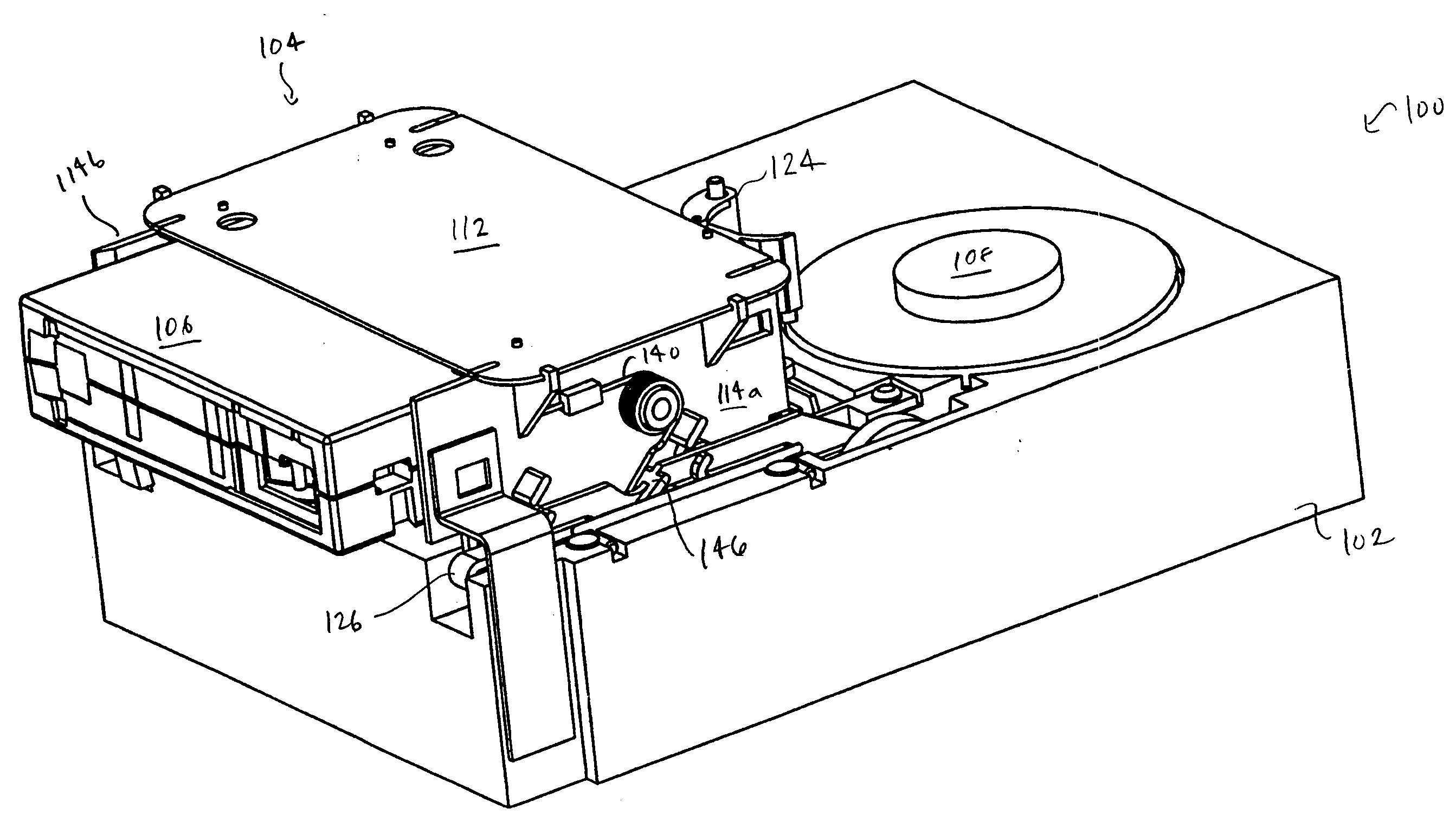
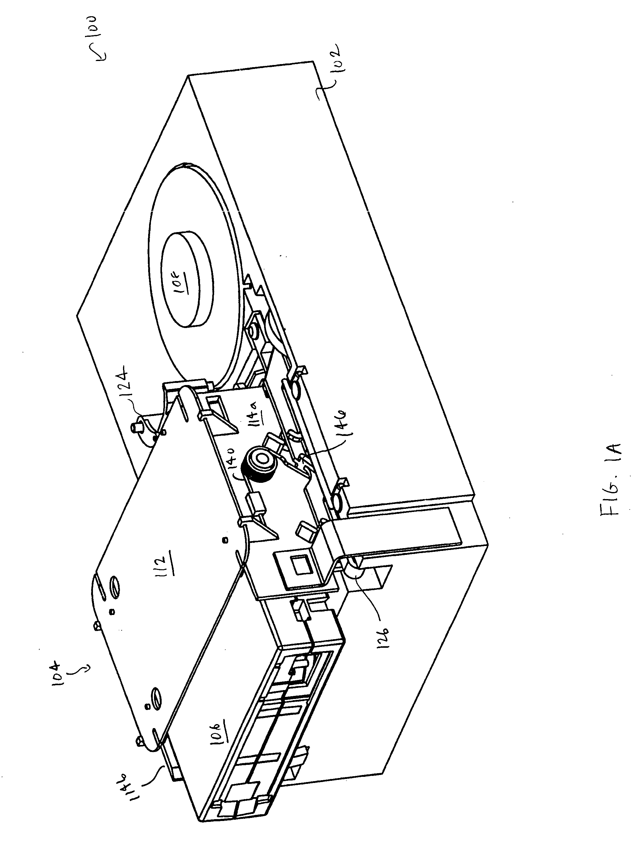
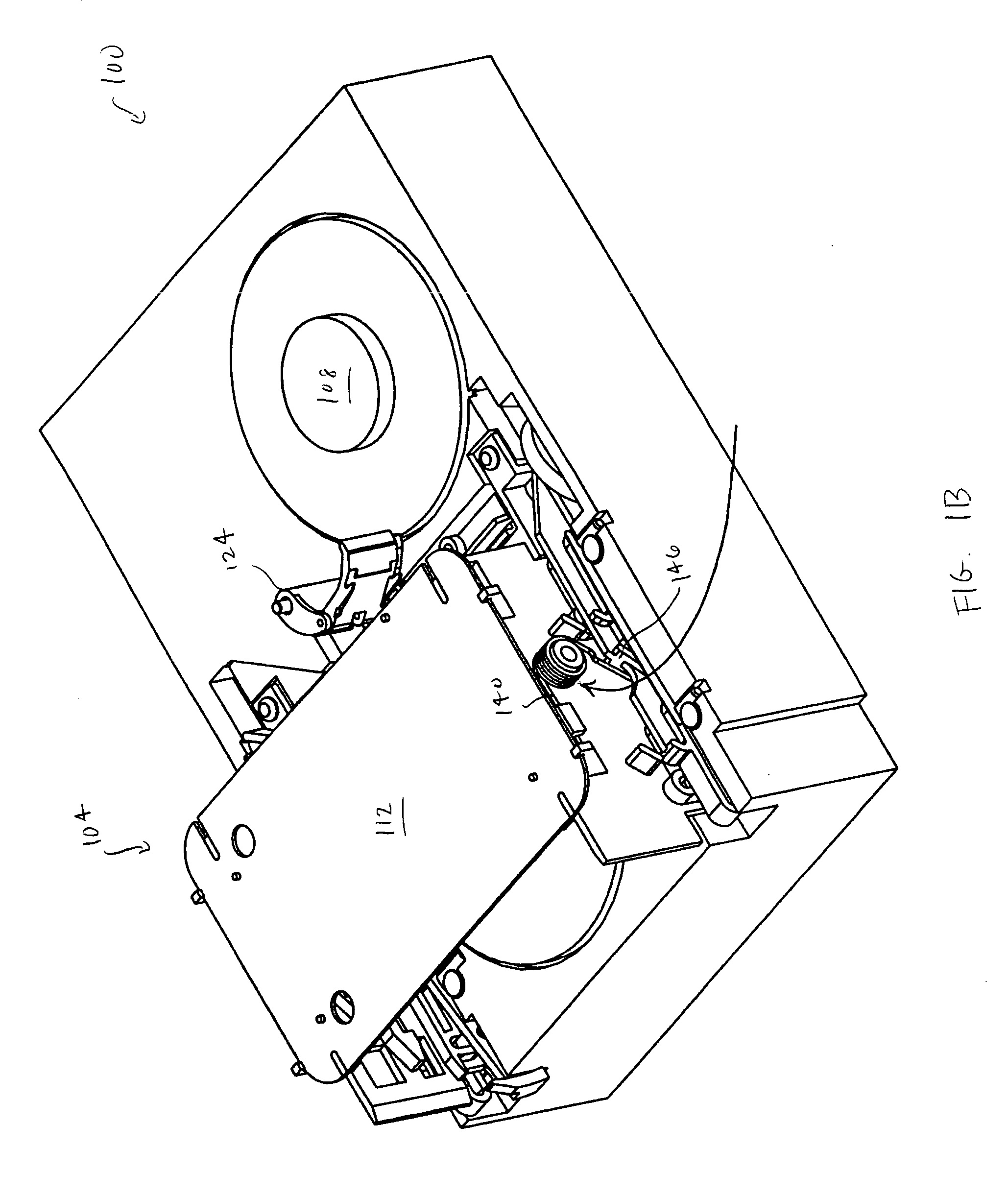
[0033]FIG. 1A shows in perspective view a tape drive system 100 in accordance with embodiments of the present invention. The tape drive 100 comprises a stationary tape drive body 102, a moving receiver 104 for receiving and translating a tape cartridge 106, and a take-up reel 108. The receiver 104 comprises a top plate 112 and two opposing side walls 114a-114b. An actuator 126 is provided adjacent to each of the side walls 114a-114b. In FTC; 1A, the receiver 104 and the tape cartridge 106 are shown in the initial load (or ejected) position. FIG. 1B is another perspective view of the tape drive system 100 with the tape cartridge 106 removed. FIG. 1C is a front view of the tape drive system 100 with the receiver 104 in the ejected position. Here, it can be seen that when the receiver 104 and tape cartridge 106 in the initial load (or ejected) position, the cartridge reel 107 (shown in FIG. 11) is not yet coupled with the reel driver 110 in the tape drive 100.

[0034] In accordance with...


PUM

PropertyMeasurementUnit
diameteraaaaaaaaaa
diameteraaaaaaaaaa
distanceaaaaaaaaaa

Abstract

A tape drive system and method of operating a tape drive system are provided. The tape drive system may include: a stationary base; at least one guide projection mounted to the stationary base; and a receiver for receiving a tape cartridge and transporting the tape cartridge from an ejected position to a loaded position, the receiver including at least one guide slot mating with one of the guide projections, each guide slot being shaped to allow the receiver to move a first distance in a horizontal direction and a second distance in a vertical direction. The method of loading a tape cartridge into a tape drive system having a stationary base and at least one guide projection mounted to the stationary base may include: receiving a tape cartridge in a receiver having at least one guide slot having a first portion and a second portion; and moving the receiver from an ejected position to a loaded position. This moving of the receiver may be performed by passing the guide projection through the first portion of the guide slot to move the receiver a first distance in a horizontal direction; and passing the guide projection through the second portion of the guide slot to move the receiver a second distance in a vertical direction.

Description

BACKGROUND OF THE INVENTION [0001] Storage subsystems, such as magnetic tape libraries, are widely used for storing information in digital form. These tape subsystems may include a storage subsystem controller for controlling one or more tape drives contained within the storage subsystem and for controlling other components of the storage subsystem, such as the tape picker, which is used to select and load tape cartridges into the tape drives. The storage subsystem may be coupled to a host system which transmits I / O requests to the storage subsystem via a host / storage connection. [0002] The tape drive reads and writes data to the primary storage medium, which can be a magnetic tape medium contained within a removable magnetic tape cartridge. The magnetic tape medium typically comprises a thin film of magnetic material which stores the data. The tape medium may be moved by the tape drive between a pair of spaced apart reels and past a data transducer to record or read back informatio...

Claims


Application Information

Patent Timeline
Patent Type & Authority Applications(United States)
IPC IPC(8): G11B15/67G11B15/675
CPCG11B15/67549G11B15/67
Inventor RATHWEG, CHRISTOPHER
Owner QUANTUM CORP
Why Eureka
Try Eureka