Antenna coil device

a technology of antenna coil and coil body, which is applied in the direction of inductance of loop antenna with ferromagnetic core, inductance with magnetic core, etc., can solve the problems of large stray capacitance, difficult noise removal, and stray capacitance between the terminal boards

Active Publication Date: 2005-03-10
SUMIDA CORP
View PDF2 Cites 2 Cited by
  • Summary
  • Abstract
  • Description
  • Claims
  • Application Information

AI Technical Summary

Benefits of technology

A size of the through hole in the width direction of the terminal board on which the through hole is provided is preferably ¾ or less of a width of the terminal board.

Problems solved by technology

Radio wave signals of radio broadcast or TV broadcast received by such a glass antenna for a vehicle is affected by noise included in an output of a battery for supplying power to the heating elements of the defogger, or the received radio wave signals which leak through a feeder to a body or a DC power supply.
In the above described automobile glass antenna coil device, the two terminal boards are placed close to and opposite each other, thereby causing stray capacitance between the terminal boards.
However, as described above, each terminal board is as wide as the coil and has a large area in order to increase the strength, thus causing large stray capacitance proportional to an area of an opposite region between the terminal boards.
Therefore, in the coil device, the terminal board is as wide as the coil and has the large area to reduce the self resonance frequency f, and reduce an impedance in, for example, a desired FM frequency band, especially in a high frequency band thereof, thereby causing difficulty in removing noise, and reducing sensitivity of an antenna.
However, a portion on which the dielectric is provided is extremely weakened, and providing a reinforcing member for reinforcing the portion increases costs resulting from an increase in the number of parts, and also causes a wide range of performance variations.
The above described problems are caused by an increase in a surface area of a conductor of opposite terminal boards of a coil device.

Method used


Image

  • Antenna coil device
  • Antenna coil device
  • Antenna coil device

Examples


Embodiment Construction

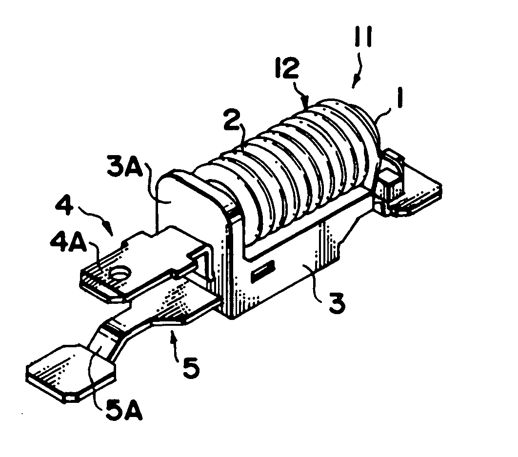
Now, an antenna coil device according to an embodiment of the present invention will be described in detail with reference to the accompanying drawings. The antenna coil device according to the embodiment removes noise (for example, output noise from a battery) in radio waves of radio broadcast or TV broadcast received by a glass antenna of an automobile, improves sensitivity of the antenna, and is connected between a battery 13 and heating elements 18 provided in a rear window 16 of the automobile, for example onto a busbar 21, as shown in FIG. 8. In the example shown in FIG. 8, wiring 20 in an upper portion of a part where the heating elements 18 is provided constitutes a radio antenna, and the heating elements 18 constitutes a TV antenna.

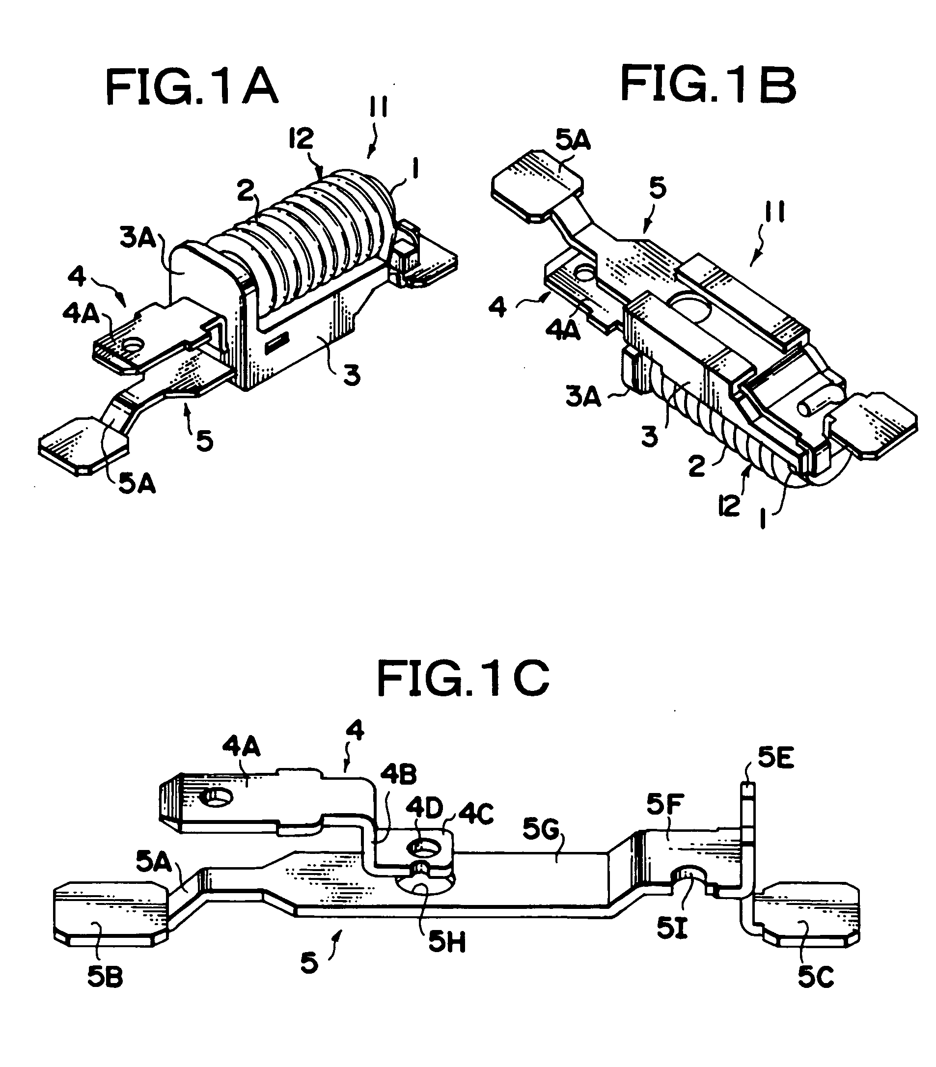
FIG. 1 shows an antenna coil device 11 according to Embodiment 1 of the present invention, and FIG. 1A is a top perspective view, FIG. 1B is a bottom perspective view, and FIG. 1C is a perspective view of terminal boards only.

As shown in FIGS...


PUM

PropertyMeasurementUnit
sizeaaaaaaaaaa
widthaaaaaaaaaa
impedanceaaaaaaaaaa

Abstract

In an antenna coil device 11, a coil portion 12 having a lead wire 2 wound around a magnetic core 1 is mounted on a case 3 made of plastic resin, and on one side of the case 3, terminal boards 4 and 5 that electrically connect one end and the other end of the lead wire 2 of the coil portion 12 to an external device are placed in a protruding manner. A through hole 4D is provided in an inserting end portion 4C of the terminal board 4, a through hole 5H is provided in a central flat portion 5G of the terminal board 5, and the two through holes 4D and 5H are placed opposite each other. This reduces stray capacitance caused between the two terminal boards 4 and 5 connected to both ends of the coil portion 12, and allows a self resonance frequency band where an impedance is equal to or above a predetermined value to be shifted to a high frequency side.

Description

RELATED APPLICATIONS This application claims the priority of Japanese Patent Application No. 2003-315173 filed on Sep. 8, 2003, which is incorporated herein by reference. BACKGROUND OF THE INVENTION 1. Field of the Invention The present invention relates to, for example, an antenna coil device, provided on a busbar of defogging heating elements of a rear window glass of a vehicle. More particularly, the present invention relates to, for example, an antenna coil device for preventing noise from being superimposed on radio broadcast signals received by an automobile glass antenna, or for improving receiving sensitivity. 2. Description of the Prior Art An automobile glass antenna has been known that uses heating elements of a defogger provided in a rear window or antenna element provided around the heating elements as an antenna for radio broadcast or TV broadcast in order to receive radio broadcast or TV broadcast in a vehicle. Radio wave signals of radio broadcast or TV broadca...

Claims


Application Information

Patent Timeline
Patent Type & Authority Applications(United States)
IPC IPC(8): H01Q1/32H01F5/04H01F17/04H01Q1/12
CPCH01F5/04H01Q1/1271H01F17/045
Inventor FUJII, HIROYUKISAITO, MASAKIMITO, TOMOKO
Owner SUMIDA CORP
Why Eureka
Try Eureka