

Liquid crystal display device and driving method for the same
a technology of liquid crystal display and driving method, which is applied in the direction of static indicating devices, television systems, instruments, etc., can solve the problems of low response speed of liquid crystal, conventional liquid crystal display devices, moving pictures, etc., and achieve the effect of improving the response tim
- Summary
- Abstract
- Description
- Claims
- Application Information
AI Technical Summary
Benefits of technology
Problems solved by technology
Method used
Image

Examples
first embodiment
[0045] [First Embodiment]
[0046] One embodiment of the present invention is described below with reference to FIGS. 1 through 6.
[0047] The present invention provides a liquid crystal display device in which a conventional picture element is divided into a plurality of divisional picture elements, that are displayed with respective luminances so as to increase the display response speed of the display area to be faster than a hypothetical display response speed before the picture element is divided. The following explains such a display device and the driving method thereof.
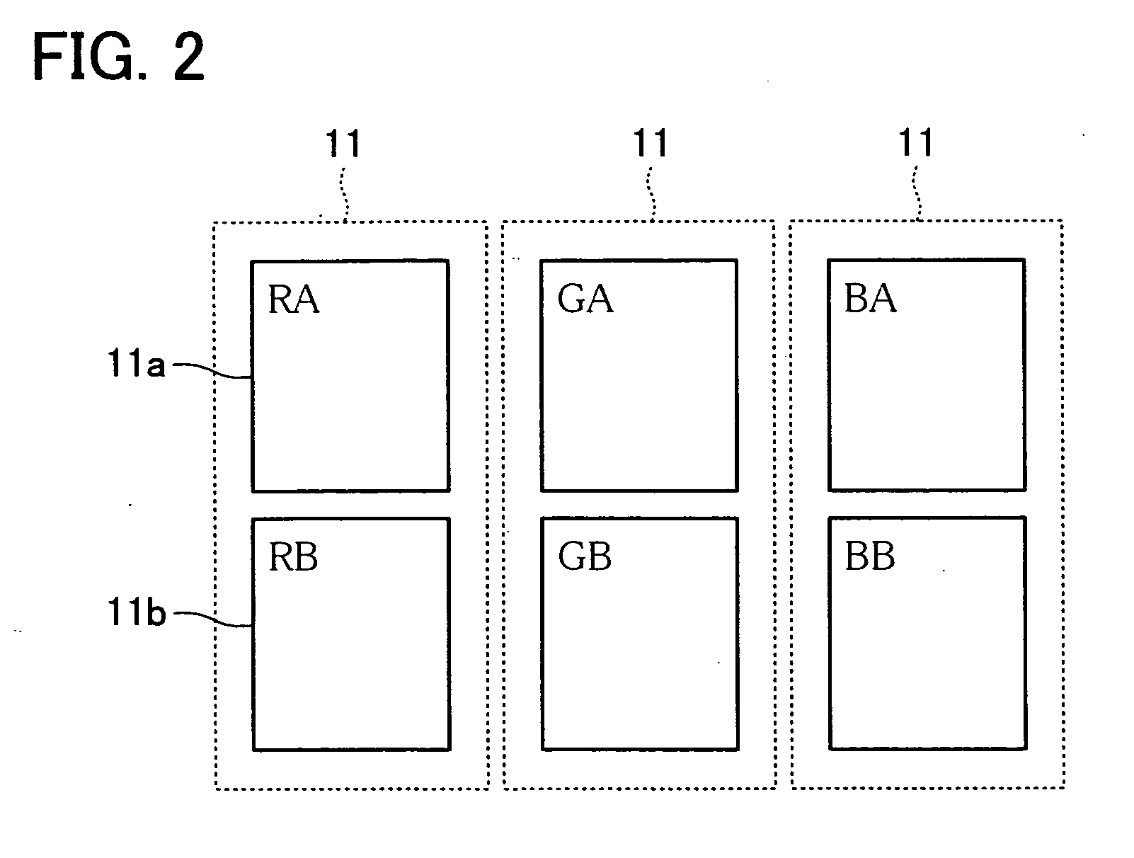
[0048] As shown in FIG. 2, the present embodiment uses picture elements 11 of Red (R), Green (G) and Blue (B), that are divided into, for example, two divisional picture elements RA / RB, GA / GB and BA / BB, respectively. The divisional picture elements RA / RB, GA / GB and BA / BB are individually driven by the respective liquid crystal elements 11a and 11b. Note that, the picture elements 11 correspond to conventional pic...
second embodiment
[0101] [Second Embodiment]
[0102] Another embodiment of the present invention is described below. Note that, any structure other than those described in the following explanation is identical to that of Embodiment 1. Therefore, for ease of explanation, materials having the equivalent functions as those shown in the drawings pertaining to Embodiment 1 above will be given the same reference symbols, and explanation thereof will be omitted here.
[0103] In addition to the structure of the liquid crystal display device of Embodiment 1, the liquid crystal display device of the present embodiment additionally uses the following algorithm in the selection process of the luminance ratios Ynorm, t, A and Ynorm, t, B, that is described in Embodiment 1.
[0104] (1) The calculation result of response time RT is checked weather or not the value is shorter than the duration of 1 frame
[0105] (2) If there are a plurality of results less than the duration of 1 frame, a result with the smallest differe...
third embodiment
[0114] [Third Embodiment]
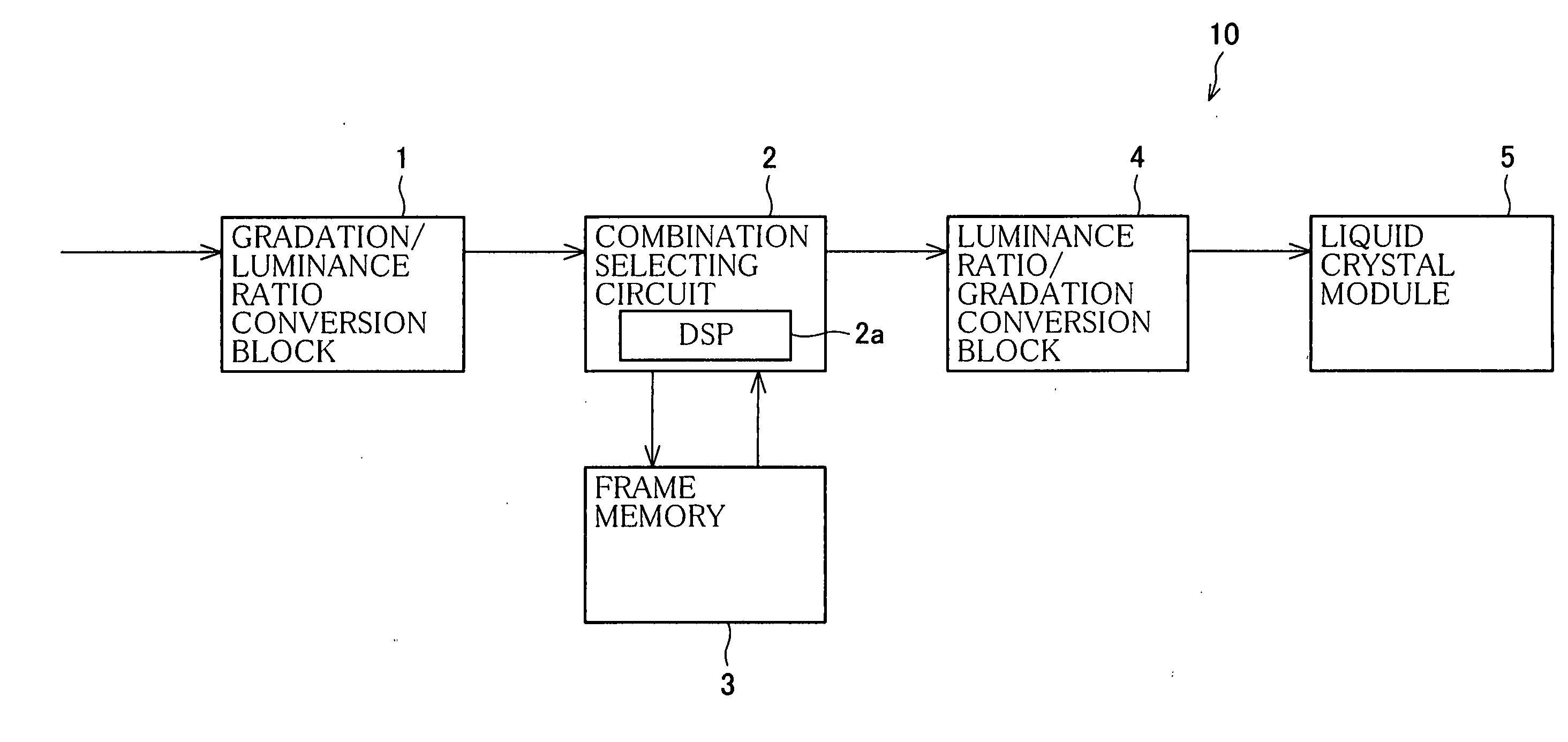
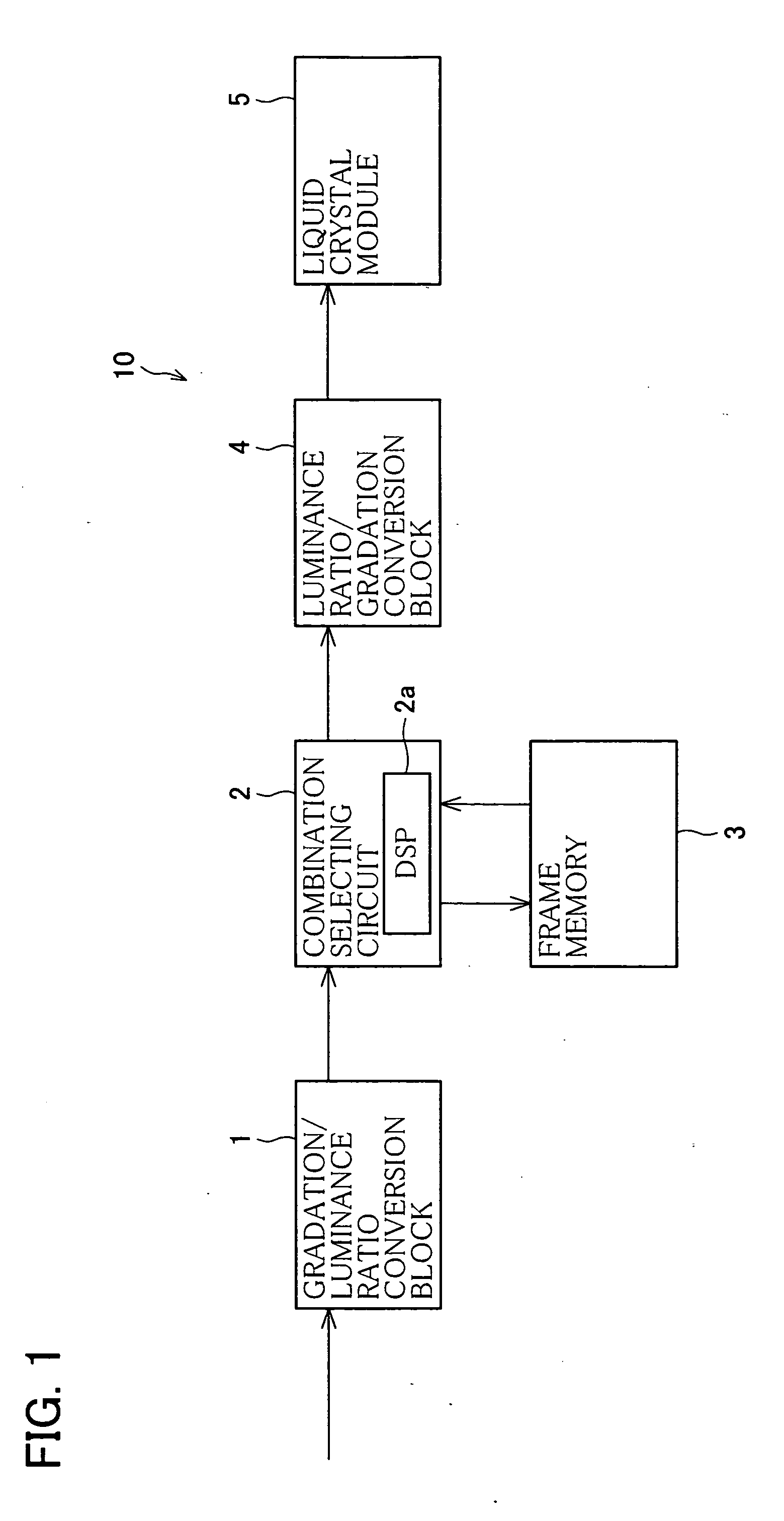
[0115] Still another embodiment of the present invention is described below with reference to FIGS. 7 and 8. The structure described in the present embodiment does not include the gradation / luminance ratio conversion block 1 and the luminance ratio / gradation conversion block 4, and instead includes a combination selecting circuit 20, that selects gradation data from a gradation data table stored in the frame memory 30 (gradation data storing means), as shown in FIG. 7.
[0116] More specifically, in the present embodiment, the frame memory 30 of the combination selecting circuit 20 stores gradation data of the liquid crystal elements 11a and 11b. However, since the table has data of the third power of color depth (input of the current frame, gradation of the immediately preceding frame of the liquid crystal element 11a, and gradation of the immediately preceding frame of the liquid crystal element 11b), the values are perceptibly large as shown in FIG. 8.
[011...
PUM
 Abstract
Description
Claims
Application Information