Sliding data buffering for image processing

Active Publication Date: 2005-03-10
TEXAS INSTR INC
View PDF8 Cites 22 Cited by
  • Summary
  • Abstract
  • Description
  • Claims
  • Application Information

AI Technical Summary

Benefits of technology

This method could employ plural input data arrays loaded into differing parts of the data buffer. These input data arrays could have differing offsets fr

Problems solved by technology

For most of these applications the amount of on-chip memory is not large enough to process an entire frame of image.
Over-processing is simple in memory management, but inefficient in computation.

Method used


Image

  • Sliding data buffering for image processing
  • Sliding data buffering for image processing
  • Sliding data buffering for image processing

Examples


Embodiment Construction

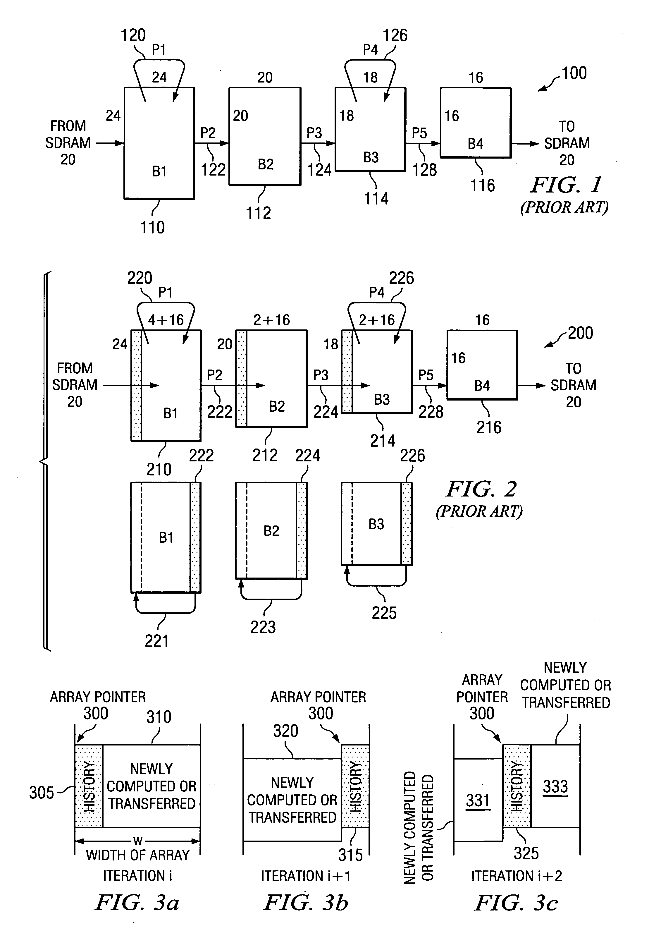
FIG. 1 illustrates a processing example 100 of the conventional over-processing approach. Data is recalled from an external memory such as synchronous dynamic random access memory (SDRAM) 20, processed and stored in a series of buffers 110 (B1), 112 (B2), 114 (B3) and 116 (B4). This processing example 100 includes five processing steps 120 (P1), 122 (P2), 124 (P3), 126 (P4) and 128 (P5). Data recalled from SDRAM 20 is initially stored in buffer 110 (B1). In this example, buffer 110 (B1) is an array of 24 by 24 pixels. Processing step 120 (P1) is an in place operation where the result is returned back to buffer 110 (B1). Processing step 122 (P2) is a filtering step. The resulting data is stored in buffer 112 (B2). Note that buffer 112 (B2) at 20 by 20 pixels is smaller than buffer 110 (B1). Thus processing step 122 (P2) needs more input that its output. Processing step 124 (P3) is another filtering step requiring more input than output. Processing step 124 (P3) inputs 20 by 20 pixel ...


PUM


Abstract

A method for managing image processing data buffers for processes having overlap input data between iterations includes loading a data buffer with an initial input data array and performing an image data array operation on the input data array. The method repeats the following steps for plural iterations including loading the data buffer with new input data forming a new input data array for a next iteration and performing the input data array operation on the new input data array. The overlap data consists of pixels at an end of each scan line. Loading new input data includes loading pixels following the overlap data for each scan line.

Description

TECHNICAL FIELD OF THE INVENTION The technical field of this invention is date buffering in data processing operations. BACKGROUND OF THE INVENTION Embedded imaging applications on cost sensitive platforms usually involve digital data processors such as generic microprocessor, digital signal processors or specialized image coprocessors working with limited amount of on-chip memory. For most of these applications the amount of on-chip memory is not large enough to process an entire frame of image. These applications typically use block processing, which is processing a small data block at a time through the processing algorithm stages. Image processing often has spatial dependency. Thus when an image is partitioned into same-sized blocks, an output block will require a larger input block. When output blocks are produced in raster-scan order, the input blocks overlap horizontally. Thus the input data for plural output blocks overlap. Furthermore, the image processing flow from input...

Claims


Application Information

Patent Timeline
IPC IPC(8): G06T1/60G09G5/39
CPCG06T1/60
Inventor HUNG, CHING-YU
Owner TEXAS INSTR INC
Why Eureka
Try Eureka