Card-cleaning assembly for card printing devices

a card printing device and card cleaning technology, applied in the field of printing devices, can solve the problems of card packaging with plastic shavings, card substrate contamination and soiling,

Active Publication Date: 2005-03-10
ZEBRA TECH CORP
View PDF12 Cites 14 Cited by
  • Summary
  • Abstract
  • Description
  • Claims
  • Application Information

AI Technical Summary

Benefits of technology

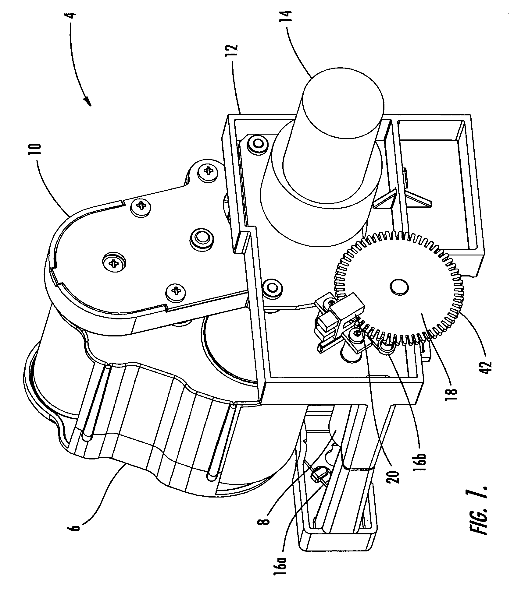
[0017] In another embodiment of the invention, a laterally-moving, non-rotatable plate member is used to clean the card material rather than a rotating cleaning roller. The pivot arm pivots so that the tape cartridge and plate member engage each other. Then, the tape can remove debris from the plate member as the tape is peeled from the lower tape core to the upper tape core and the plate member translates without rotation.

Problems solved by technology

One problem with conventional thermal printers and thermal printing processes is the contamination and soiling of card substrates.
The cards can be contaminated in a number of ways.
This cutting operation can leave plastic shavings in the card packaging.
Also, once the cards are removed from their packages, they are susceptible to air-borne contaminants such as dirt and dust particles.
When the cover of the thermal printer is open, debris can fall into the printer and land on the cards.
Air is circulated within printers, and this air can blow foreign matter onto the surfaces of the cards.
Card contamination creates several problems.
For example, if the image is printed on a card surface loaded with dust and dirt particles and these particles fall off before lamination of the card, then the image under the particles may be lost.
If the particles remain adhered to the surface, then defects may appear in the image, and the print quality may be poor.
The dust and dirt particles can also damage the elements of the print head so that even after the element is cleaned, it will not transfer dye.
Contaminates trapped between the card and the laminate film will create bubbles that reduce the overall quality of the printed card.
Although the tape assembly described in the '076, '316, and '160 Patents is effective in removing dirt and dust particles from the silicone roller, the assembly has some disadvantageous features.
It can be difficult and time-consuming to replace the cleaning tape, since the tape must be threaded along this complex path in each instance.
Further, the tape can rip or jam during the cleaning process.

Method used


Image

  • Card-cleaning assembly for card printing devices
  • Card-cleaning assembly for card printing devices
  • Card-cleaning assembly for card printing devices

Examples


Embodiment Construction

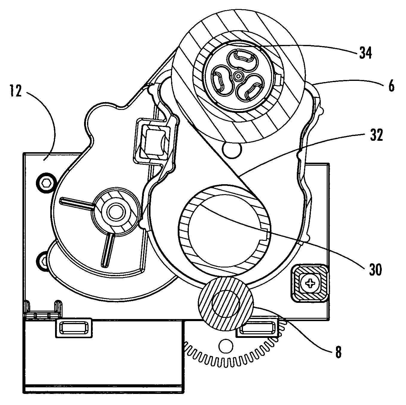
[0033] The card-cleaning assembly of the present invention can be used in any card printing apparatus. The cleaning assembly is particularly suitable for use in a thermal card printer. In general, a thermal card printer uses a thermal dye sublimation printing process to thermally transfer dyes onto a card substrate. The dyes can be used to print any indicia (for example, letters, numbers, symbols, photographs, and the like) on the surface of the card substrate.

[0034] Thus, the thermal printing process can be used to produce a wide variety of card materials, for example, passports, visas, driver's licenses, employee badges, student cards, credit cards, bank cards, security access cards, and the like. The card substrate, which is printed with the indicia, can be made from any suitable material. Examples of suitable dye-receiving card materials include plain papers and films made from polyesters, vinyls (for example, polyvinyl chloride and polyvinyl acetate), polyamides, polyolefins (...


PUM


Abstract

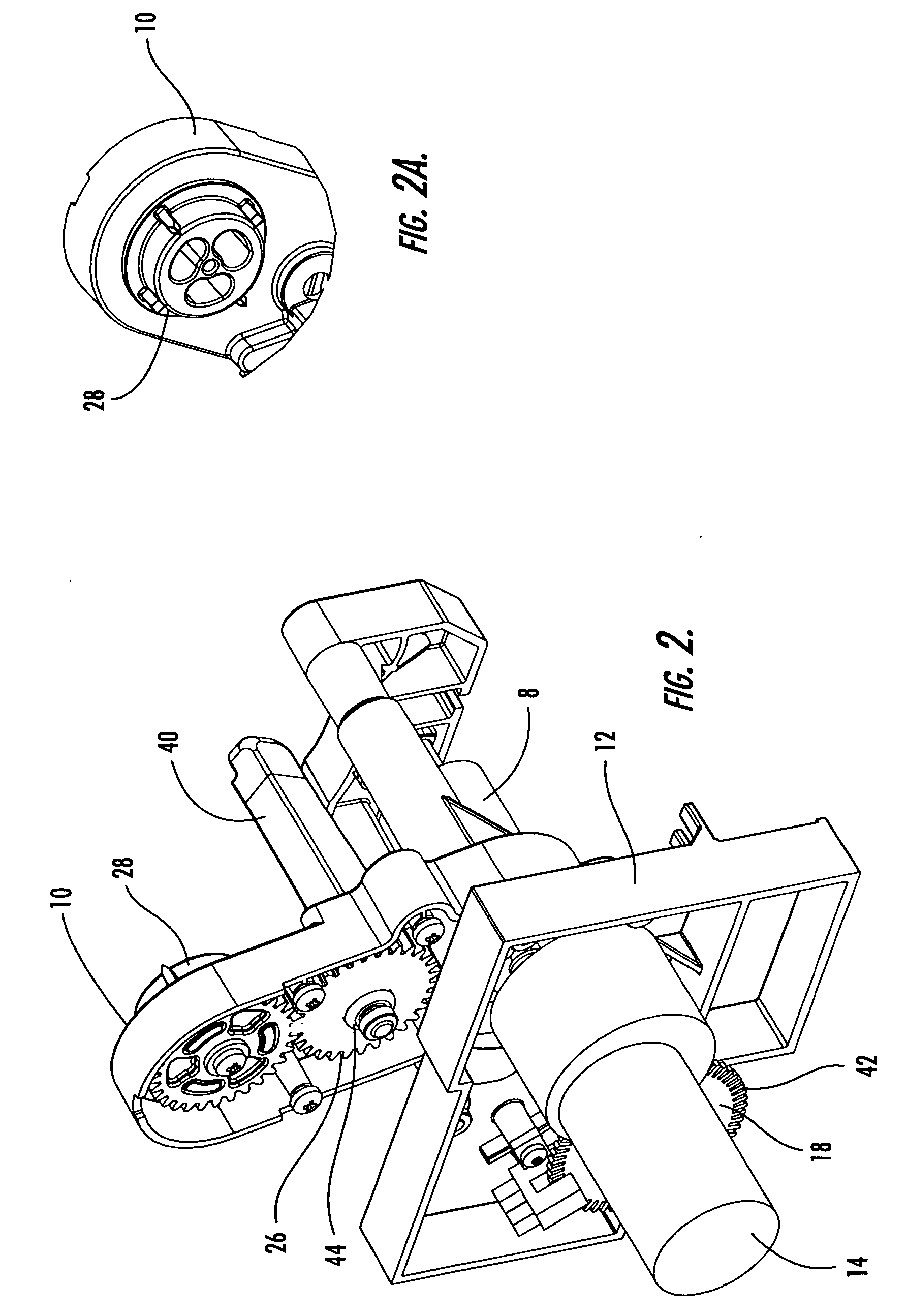
A card-cleaning assembly for printers is provided. The assembly can be used in any suitable card printing apparatus, particularly thermal dye printers. Such card printers are used to print driver's licenses, employee badges, student cards, and the like. The assembly includes a card-cleaning roller and an adhesive tape cartridge. The cleaning roller contacts the card and removes dust and dirt particles and other debris from the surface of the card. The tape cartridge is attached to a pivoting arm on the printer which pivots so that the adhesive tape engages the cleaning roller and removes the debris from the roller as the roller rotates.

Description

CROSS-REFERENCE TO RELATED APPLICATIONS [0001] This application claims the benefit of U.S. Provisional Patent Application No. 60 / 500,588 having a filing date of Sep. 5, 2003, the entire contents of which are hereby incorporated by reference.BACKGROUND OF THE INVENTION [0002] The present invention relates generally to a printing apparatus for producing images on card substrates such as driver's licenses, employee badges, student cards, and the like. More particularly, the invention relates to a card-cleaning assembly for use in card printers, particularly thermal card printers. The assembly includes a card-cleaning roller and adhesive tape cartridge. [0003] There are various known card printing apparatus which use a thermal printing process for producing colored images on card materials. In general, these printing devices use a conventional thermal dye transfer printing method, wherein a thermal printing head thermally-transfers dyes from a dye ribbon to a surface of the card. The th...

Claims


Application Information

Patent Timeline
Patent Type & Authority Applications(United States)
IPC IPC(8): B08B1/00B08B7/00B41J13/12B41J29/17B41J29/38
CPCB08B1/007B08B7/0028B41J29/38B41J29/17B41J13/12
Inventor HELMA, THOMAS R.JONES, TERRENCE K.MAYNARD, RAYMOND E.
Owner ZEBRA TECH CORP
Why Eureka
Try Eureka