

Ink jet head and ink jet recording apparatus
a recording apparatus and ink jet technology, applied in the direction of printing, other printing apparatus, etc., can solve the problems of increasing the cost of the driving circuit inevitably, the recording precision is not sufficiently high, and the recording accuracy is not high enough, so as to reduce the variation of the signal supplied, shorten the lead wire, and improve the ink discharging performance
- Summary
- Abstract
- Description
- Claims
- Application Information
AI Technical Summary
Benefits of technology
Problems solved by technology
Method used
Image

Examples
embodiment 1
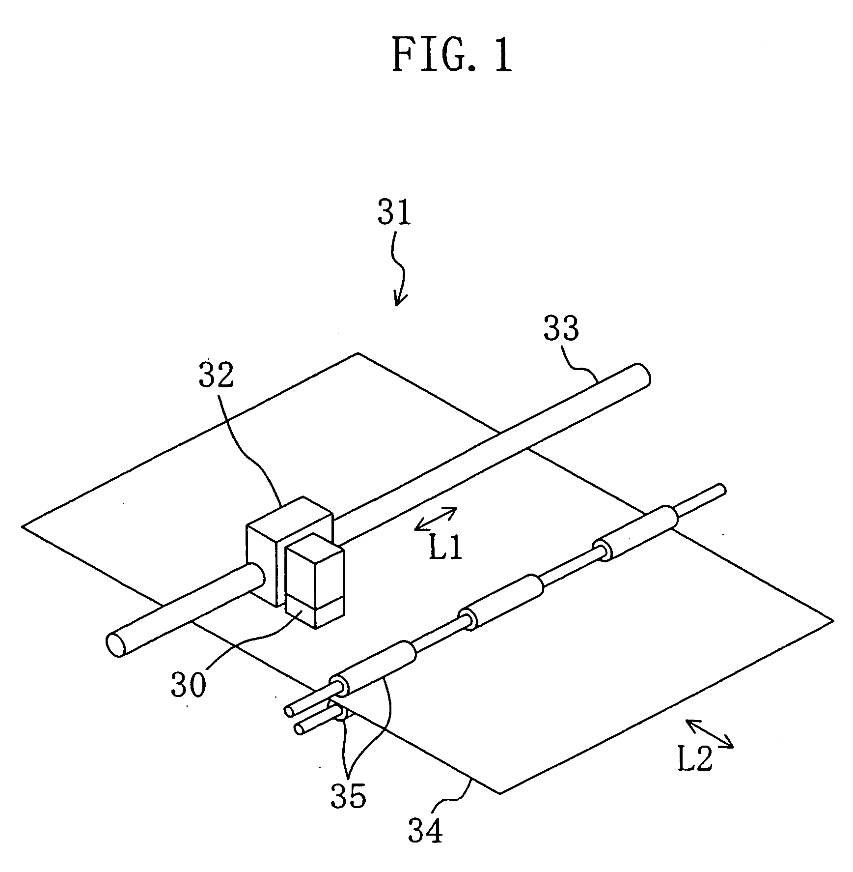
[0089]FIG. 1 schematically illustrates an important part of an ink jet printer 31 including an ink jet head 30 according to the present embodiment. The ink jet head 30 is attached to a carriage 32 that is provided with a carriage motor (not shown). The carriage 32 is reciprocated by the carriage motor in the direction labeled “L1” in the figure while being guided by a carriage shaft 33 extending in the direction L1. Thus, the ink jet head 30 is reciprocated in the direction L1.
[0090] Recording paper 34 is sandwiched between two carrier rollers 35, which are rotated by a carrier motor (not shown), and is carried by the carrier motor and the carrier rollers 35 in the direction labeled “L2” in the figure, which is perpendicular to the direction L1.
[0091] The carriage 32 and the carriage motor together form movement means for the direction L1. The carrier rollers 35 and the carrier motor together form movement means for the direction L2.
[0092] Note however that the recording apparatu...
embodiment 2
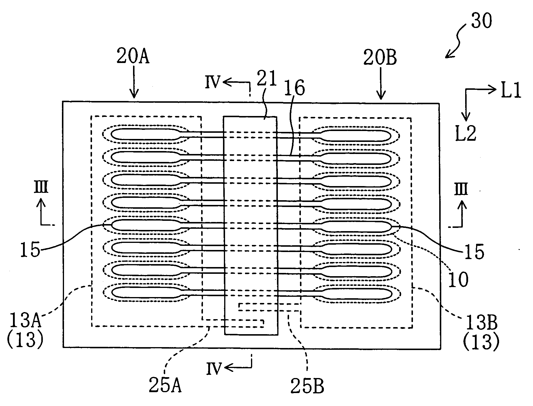
[0110] The ink jet head 30 according to Embodiment 2 includes four actuator columns with two relay terminal sections provided on opposite sides of the array of the four actuator columns, as illustrated in FIG. 7.
[0111] The first to fourth actuator columns 20A to 20D extend in the vertical direction and each include a plurality of actuators 20, and the actuator columns 20A to 20D are arranged next to each other in the horizontal direction. A first relay terminal section 21A is provided on the left side of the first actuator column 20A, and a second relay terminal section 21B is provided on the right side of the fourth actuator column 20D.
[0112] Each recording electrode 15 of the first actuator column 20A is connected to the first relay terminal section 21A via the lead wire 16 extending in the horizontal direction. Moreover, the recording electrode 15 of the first actuator column 20A and the recording electrode 15 of the second actuator column 20B that belong to the same row are co...
embodiment 3
[0117] In Embodiment 2, the relay terminal sections 21A and 21B are provided on opposite sides of the array of actuator columns. Alternatively, the relay terminal sections 21A and 21B may be provided in inter-column spaces between actuator columns.
[0118] In Embodiment 3, the first relay terminal section 21A is provided between the first actuator column 20A and the second actuator column 20B, and the second relay terminal section 21B is provided between the third actuator column 20C and the fourth actuator column 20D, as illustrated in FIG. 9B.
[0119] Each of nozzles 17A to 17D is provided on one side of the pressure chamber 10 that is closer to the nearest relay terminal section in the horizontal direction. Specifically, the nozzle 17A associated with the first actuator column 20A is provided on one side of the pressure chamber 10 that is closer to the second actuator column 20B, and the nozzle 17B associated with the second actuator column 20B is provided on one side of the pressu...
PUM
 Abstract
Description
Claims
Application Information