Image-taking apparatus and focus control program for image-taking apparatus

a technology of image-taking apparatus and focus control, which is applied in the field of focus control in the image-taking apparatus, can solve the problems of taking a long time to achieve an in-focus state, and achieve the effect of improving the accuracy of re-performance (restart) determination and reliably maintaining an in-focus sta

Inactive Publication Date: 2005-03-10
CANON KK
View PDF25 Cites 33 Cited by
  • Summary
  • Abstract
  • Description
  • Claims
  • Application Information

AI Technical Summary

Benefits of technology

It is an object of the present invention to provide an image-taking apparatus capable of improving the accuracy of re-performance (restart) determination of in-focus search control to reliably maintain an in-focus state in response to a condition change after focusing is achieved in performing focus control which uses a focus evaluation value signal to search for an in-focus position (for example, the TV-AF method), and a control program for the image-taking apparatus.

Problems solved by technology

If the distance to an object is largely changed, it may take a long time to attain an in-focus state.

Method used


Image

  • Image-taking apparatus and focus control program for image-taking apparatus
  • Image-taking apparatus and focus control program for image-taking apparatus
  • Image-taking apparatus and focus control program for image-taking apparatus

Examples


embodiment 1

(Embodiment 1)

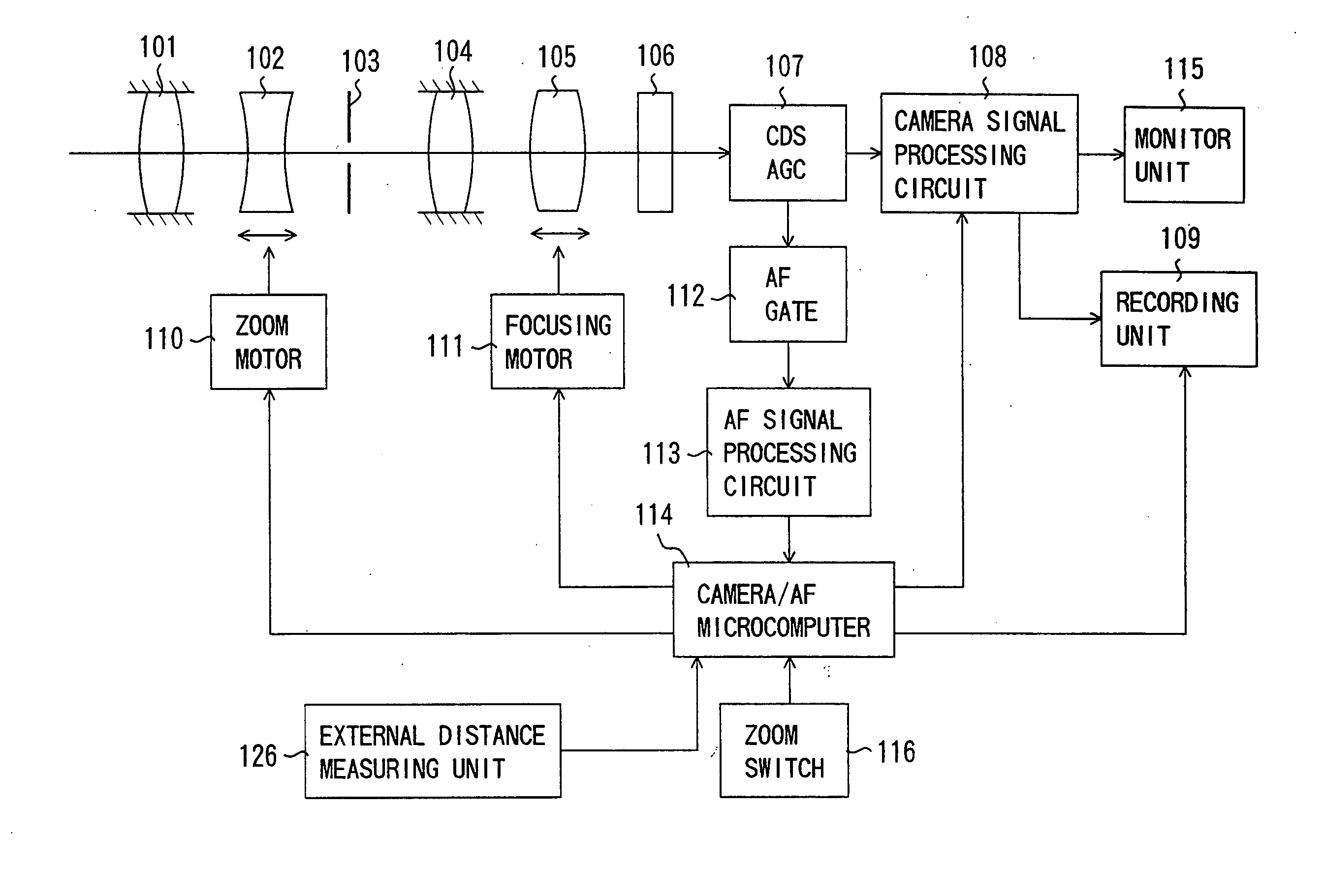
FIG. 1 shows the structure of a video camera (an image-taking apparatus) which is Embodiment 1 of the present invention. While Embodiment 1 is described in connection with a video camera integral with an image-taking lens, the present invention is applicable to a video camera on which an image-taking lens is mountable. In this case, a control signal produced by a camera / AF microcomputer, later described, is communicated to a microcomputer in the image-taking lens such that the camera / AF microcomputer controls the drive of a focus lens unit through the lens microcomputer. In addition, while Embodiment 1 is described in connection with the video camera, the present invention is applicable to various types of image-taking apparatuses such as a digital still camera. This applies to Embodiment 2, later described.

In FIG. 1, reference numeral 101 shows a first fixed lens unit, reference numeral 102 shows a lens unit (hereinafter referred to as a zoom lens unit) which provid...

embodiment 2

(Embodiment 2)

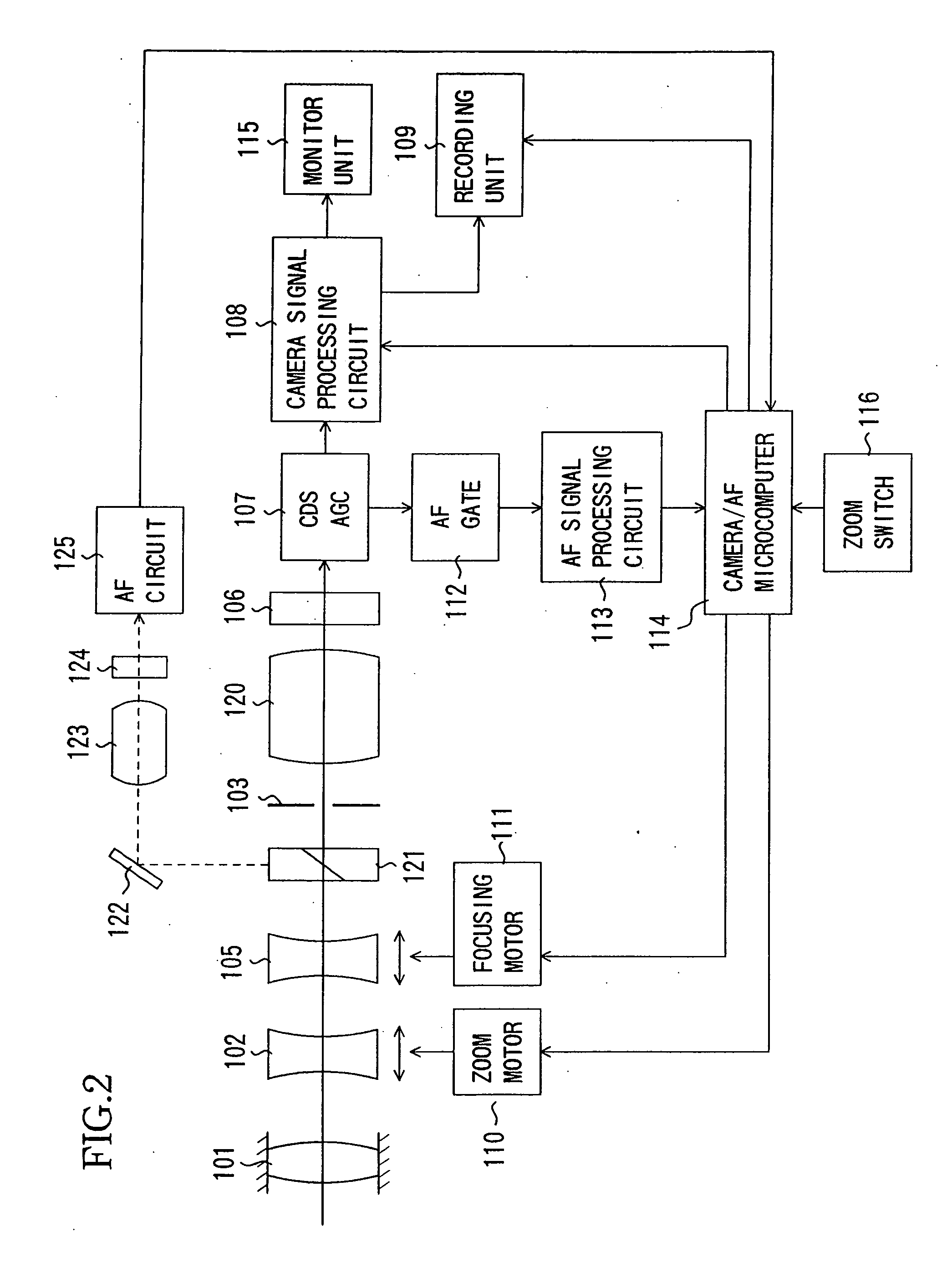
FIG. 2 is a block diagram showing the system structure of a video camera (an image-taking apparatus) which is Embodiment 2 of the present invention. In Embodiment 2, components identical to those in Embodiment 1 described above are designated with the same reference numerals and the description thereof is omitted.

While Embodiment 1 has been described for the case where the external distance measuring unit 126 is used as the second detecting means, Embodiment 2 is described for the case where a TTL (through the lens) phase difference detection unit is used.

An image-taking optical system of Embodiment 2 is formed of a first fixed lens unit 101, a zoom lens unit 102, a focus lens unit 105, a stop 103, and an image-forming lens unit 120, disposed in order from an object side (the left side in FIG. 2). The image-taking optical system constituted by these lens units is a rear focus optical system formed of the four lens units having a positive, a negative, a negative, a ...


PUM


Abstract

An image-taking apparatus is disclosed which enables the accuracy of re-performance determination of in-focus search control to reliably maintain an in-focus state in response to a condition change after focusing is achieved. The image-taking apparatus comprise a first detector which outputs a focus evaluation value signal and a second detector which outputs a detection signal different from the focus evaluation value signal. The image-taking apparatus comprises a controller which performs a first control for controlling drive of the focus lens such that an in-focus position of the focus lens is searched for on the basis of the focus evaluation value signal. The controller obtains shift information which represents a shift state from an in-focus state based on the detection signal from the second detector after the first control, and performs processing associated with the re-performance of the first control based on at least the shift information.

Description

BACKGROUND OF THE INVENTION 1. Field of the Invention The present invention relates to focus control in an image-taking apparatus. 2. Description of the Prior Art A so-called TV-AF method is mainly used for auto-focus (AF) in video cameras. In the TV-AF method, an object image is photoelectrically converted by an image-pickup element or the like into a video signal from which a high-frequency component representing the sharpness of the video is extracted through a band pass filter, and the drive of a focus lens is controlled to search for the position at which an AF evaluation value indicating the sharpness is at the maximum. As shown in FIG. 5, the position at which the AF evaluation value is at the maximum corresponds to an in-focus position. When focusing is thus achieved, the AF evaluation value at that point is stored. Then, an AF evaluation value taken after the focusing is compared with the stored AF evaluation value (that is, determination of restart is made), and if a ...

Claims


Application Information

Patent Timeline
Patent Type & Authority Applications(United States)
IPC IPC(8): G02B7/08G03B13/36G02B7/10G02B7/28G02B7/34G02B7/36H04N5/232
CPCH04N5/232G02B7/102H04N23/673H04N23/959
Inventor ISHII, KAZUNORI
Owner CANON KK
Why Eureka
Try Eureka