Light emitting diode carrier

a technology of light-emitting diodes and lamp assemblies, which is applied in the direction of lighting and heating apparatus, lighting support devices, instruments, etc., can solve the problems of difficult to achieve consistent mounting, design problems, and insufficient esthetics, so as to improve the efficiency of the lamp and reduce the probability of damaging the led. , the effect of improving the efficiency

Active Publication Date: 2005-03-10
VALEO SYLVANIA L L C
View PDF4 Cites 16 Cited by
  • Summary
  • Abstract
  • Description
  • Claims
  • Application Information

AI Technical Summary

Benefits of technology

[0009] This lamp assembly provides numerous advantages over the prior art. Clear optics can be used in front of the light sources, which, of course, preferably are LEDs, since only the carrier and LEDs are visible from the front. The carrier can be made of any color or texture to enhance the design. Heat staking or other attachment method gets performed on the metal heat sink, lowering the probability of damaging an LED during the attachment process. The heat sinks are open to the air, thus increasing their efficiency. The flexible PCB is sandwiched between the carrier and the heat sinks leading to a more robust design. The tolerances involved in the heat sinks and the PCB thickness do not add to the tolerance of the LED focal point position. And, the LEDs are partially “caged”, that is, by being mounted within the passages in the carrier, they are much less likely to sustain damage during lamp assembly or transport.

Problems solved by technology

Design problems have occurred when using these lamps because of the mounting requirements and the esthetics being undermined by the visibility of the circuit board and various electrical connections.
Additionally, it has been difficult to achieve consistent mounting without damaging the LEDs themselves, and in mounting the required heat sinks, which often were trapped between the printed circuit board (PCB) and a carrier, reducing the heat sink access to air and adversely effecting their cooling function.
Still other problems arose because of the tolerance build-up between PCBs, carriers and heat sinks, which tolerances added to the LED focal point positional tolerance making it more difficult to achieve the desire optical performance, particularly where additional optics, such as Fresnel lenses, were being used.
If reflector cups were used with the LEDs it was possible for the PCB to come into contact with the metallized reflectors, posing a risk for short circuits and failure of the lamp assembly.

Method used


Image

  • Light emitting diode carrier
  • Light emitting diode carrier

Examples


Embodiment Construction

[0011] For a better understanding of the present invention, together with other and further objects, advantages and capabilities thereof, reference is made to the following disclosure and appended claims in conjunction with the above-described drawings.

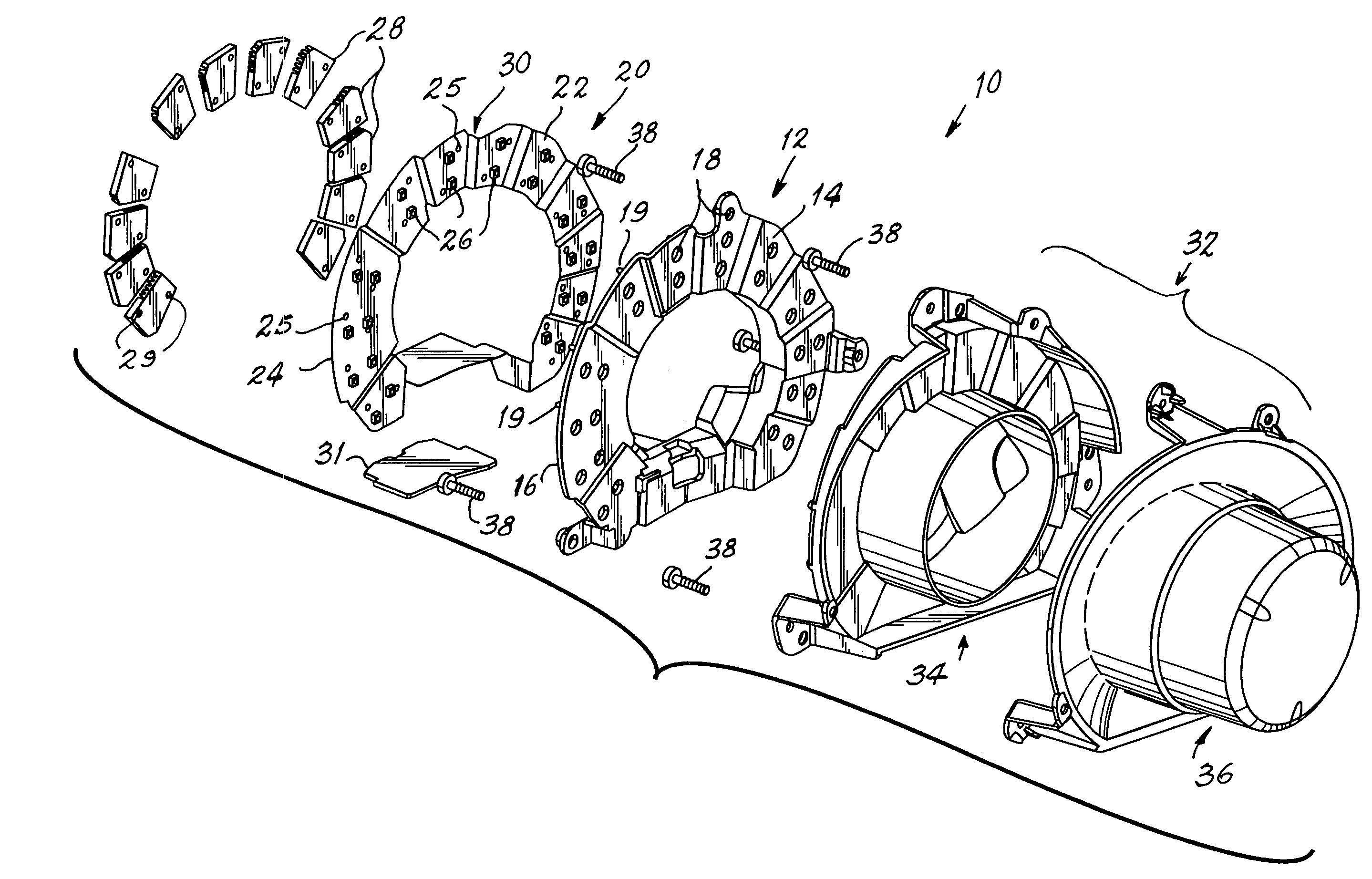
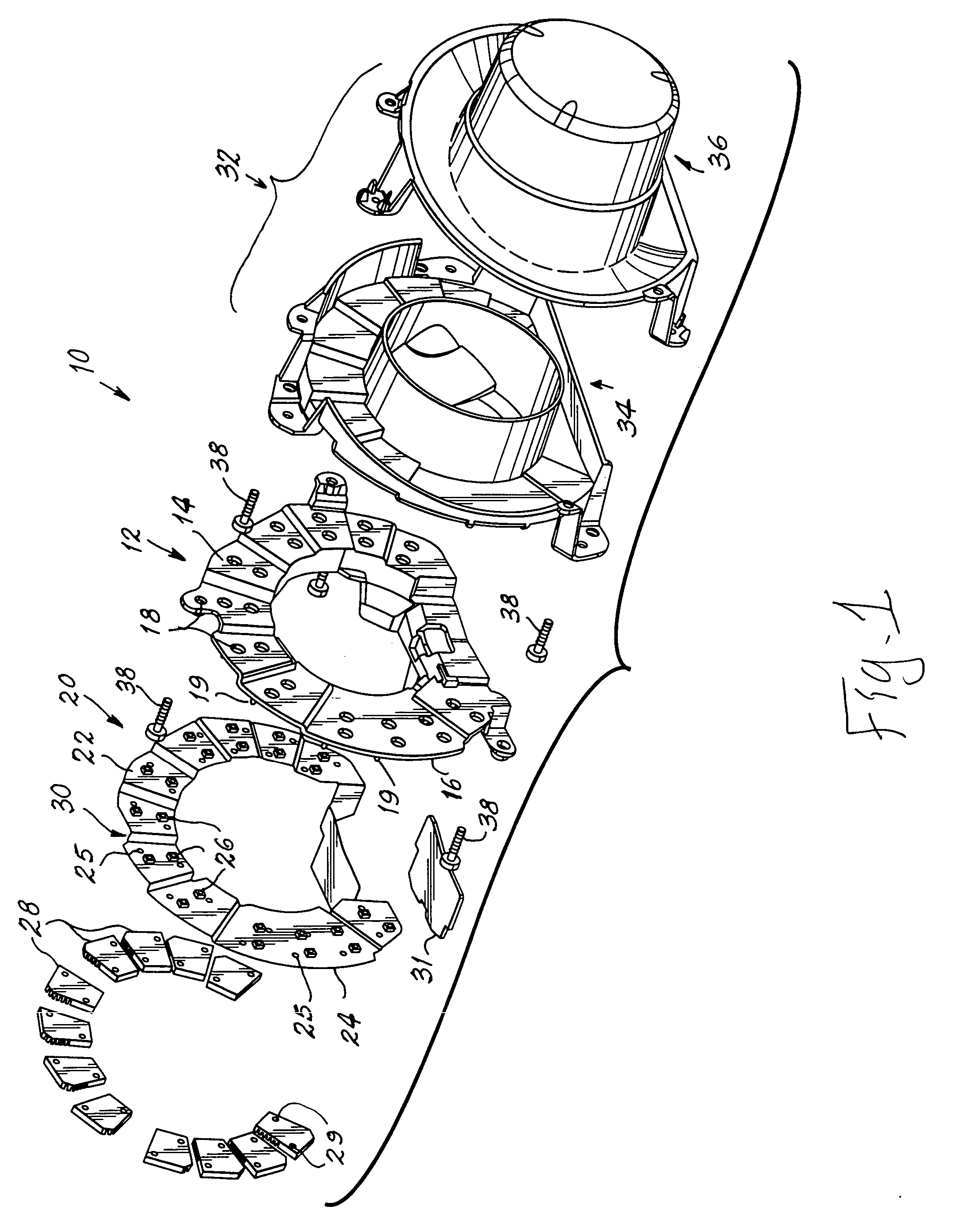
[0012] Referring now to FIG. 1 with greater particularity, there is shown a lamp assembly 10 that comprises a substantially annular carrier 12 having a front side 14 and a backside 16. The carrier 12 can be provided with step portions 30 that extend in separate planes and is provided with a plurality of passages 18 therethrough. A plurality of heat stakes 19 project from back side 16 and are used to attach the various parts of the assembly, as will be shown hereafter.

[0013] A printed circuit board (PCB) 20, which is preferably flexible and includes a configuration substantially matching that of the carrier 12, includes a first surface 22 and a second surface 24, the former being provided with the necessary electrical circuitry. Aper...


PUM


Abstract

A lamp assembly (10) has a carrier (12) with a front side (14) and a backside (16) provided with a plurality of passages (18) therethrough. A circuit board (20) includes a first surface (22) and a second surface (24). A plurality of light sources (26) is mounted on the first surface (22), and the first surface (22) of the circuit board (20) is aligned with the backside (16) of the carrier (12). The plurality of light sources (26) is aligned with the plurality of passages (18) in one-to-one relationship. At least one heat sink (28) is mounted in thermal contact with at least one of the plurality of light sources.

Description

TECHNICAL FIELD [0001] This invention relates to lamp assemblies and more particularly to lamp assemblies for use with automobiles. Still more particularly the invention relates to lamp assemblies employing light emitting diodes (LEDs) and flexible circuit boards uniquely mounted upon a carrier. BACKGROUND ART [0002] The use of LEDs has dramatically increased in recent years, particularly for automotive uses, because of their long life and relatively low direct current power consumption. A prime example has been the use of LED lamps for the high mount taillight required on automobiles and light trucks. Design problems have occurred when using these lamps because of the mounting requirements and the esthetics being undermined by the visibility of the circuit board and various electrical connections. [0003] Additionally, it has been difficult to achieve consistent mounting without damaging the LEDs themselves, and in mounting the required heat sinks, which often were trapped between t...

Claims


Application Information

Patent Timeline
Patent Type & Authority Applications(United States)
IPC IPC(8): B60Q1/26F21K99/00F21S8/04F21S8/10F21V5/04F21V19/00F21V29/00F21W101/14F21Y101/02H01L33/00H05K1/02
CPCF21K99/00F21S48/212F21S48/215F21V29/713F21V29/004F21Y2101/02Y10S362/80F21S48/328F21V15/02F21Y2115/10F21S43/195F21S43/14F21S45/47F21V29/70
Inventor COLIP, MATTHEW S.BAKER, BRADLEY T.
Owner VALEO SYLVANIA L L C
Why Eureka
Try Eureka