Burner fuel mixer head for concurrently burning two gaseous fuels

a technology of burner fuel and mixer head, which is applied in the direction of burners, combustion types, combustion processes, etc., can solve the problems of uneven heat in the firetube and unacceptable levels of emissions, and achieve the effect of effectively drawing combustion air

Inactive Publication Date: 2005-03-10
THE IDEA PLACE
View PDF4 Cites 23 Cited by
  • Summary
  • Abstract
  • Description
  • Claims
  • Application Information

AI Technical Summary

Benefits of technology

[0010] It is also preferred that a venturi effect be created in the fuel/air mixing chamber so that it draws combustion air

Problems solved by technology

However, stricter environmental regulations have placed limits on venting and flaring, which has lead to the use of this low pressure raw gas as a fuel supply for firetube burners used in various oil processing equipment.
Burning raw gas a

Method used


Image

  • Burner fuel mixer head for concurrently burning two gaseous fuels
  • Burner fuel mixer head for concurrently burning two gaseous fuels
  • Burner fuel mixer head for concurrently burning two gaseous fuels

Examples


Embodiment Construction

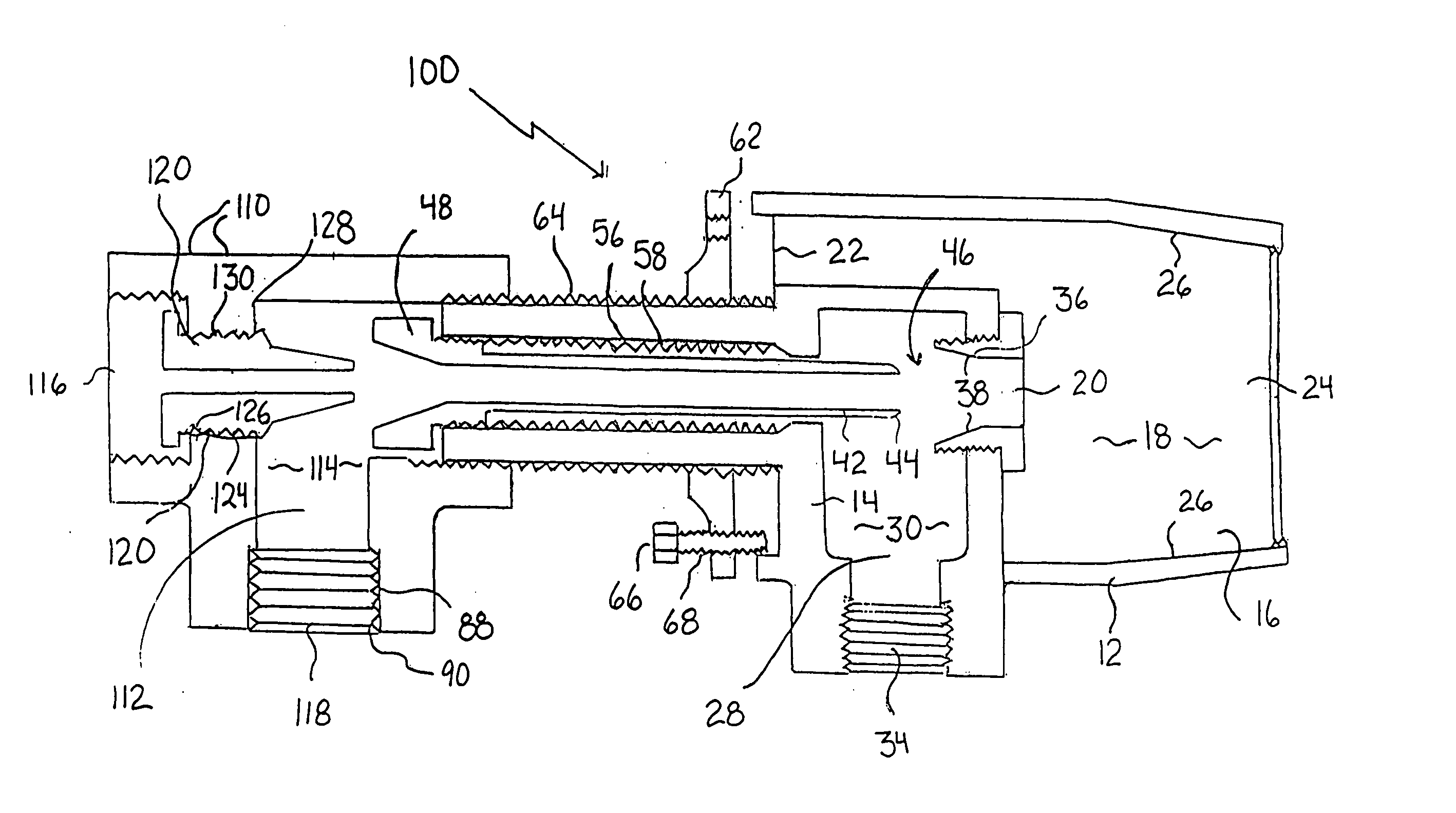
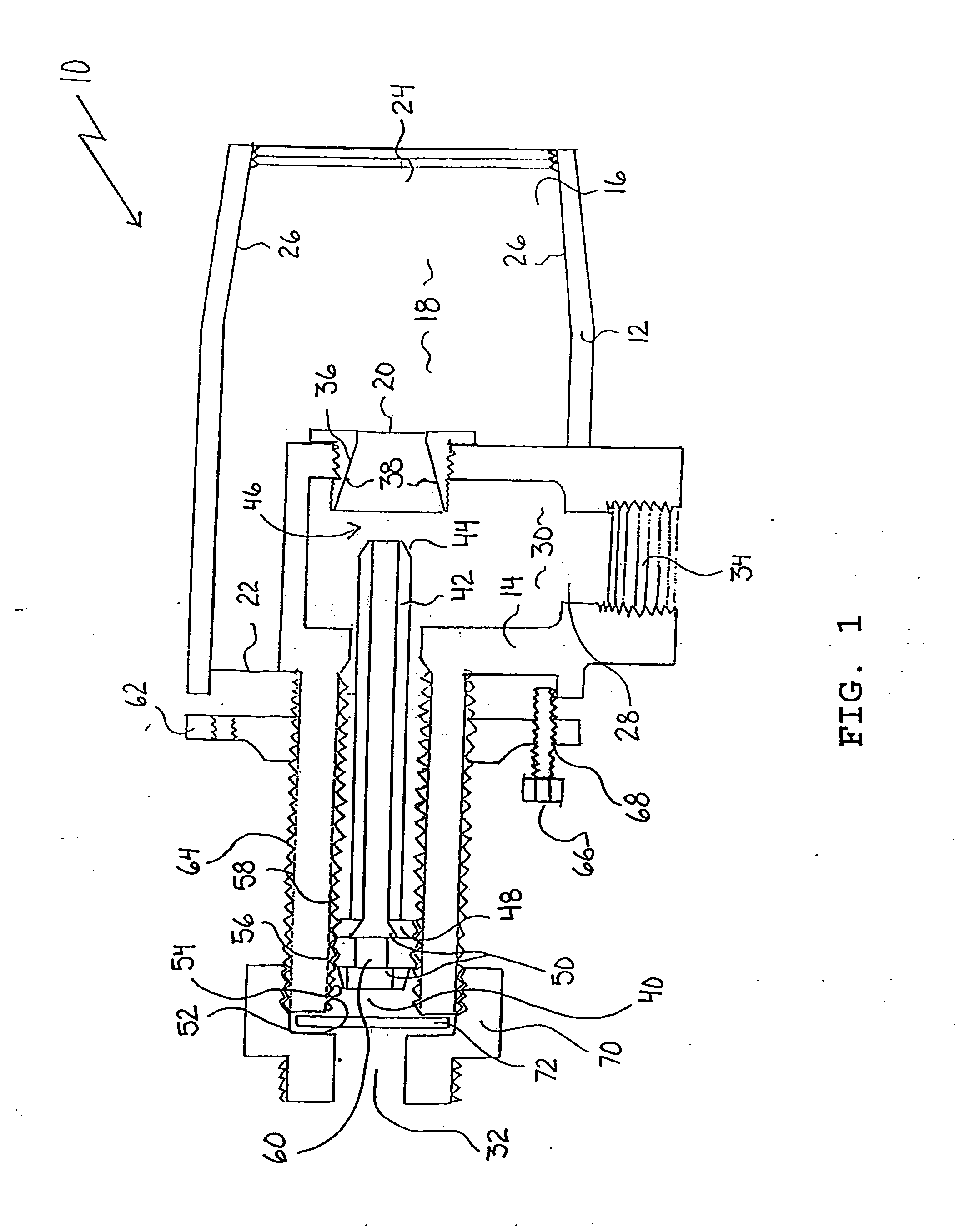
[0014] The preferred embodiment, a burner fuel mixer head generally identified by reference numeral 10, will now be described with reference to FIG. 1.

[0015] Structure and Relationship of Parts:

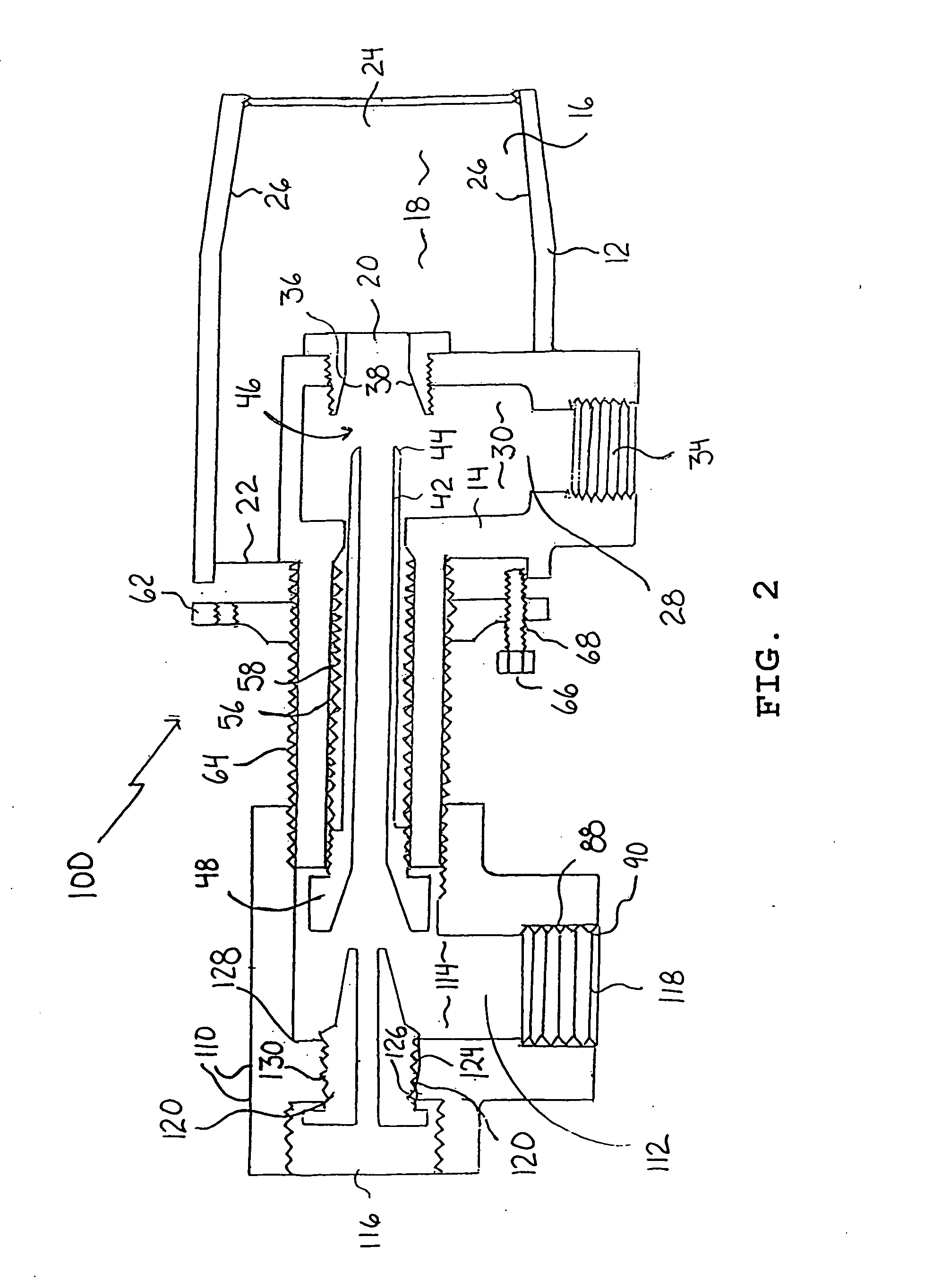
[0016] Referring to FIG. 1, there is provided a burner fuel mixer head 10 which includes a primary housing 12 and a secondary housing 14. Primary housing 12 has an interior cavity 16 that defines a fuel / air mixing chamber 18. Primary housing 12 has a mixed fuel gas inlet 20, a combustion air inlet 22, and a mixed fuel / air outlet 24 all of which communicate with interior cavity 16. Mixed fuel / air outlet 24 of primary housing 12 has converging sidewalls 26.

[0017] Secondary housing 14 has an interior cavity 28 that also defines a fuel mixing chamber 30. Interior cavity 28 of secondary housing 14 communicates with mixed fuel gas inlet 20 leading into primary housing 12. Secondary housing 14 has a pressurized fuel gas inlet 32 and a low pressure fuel gas inlet 34.

[0018] A venturi throat 36 wit...


PUM


Abstract

A burner fuel mixer head includes a primary housing and a secondary housing. The primary housing has a fuel/air mixing chamber with a mixed fuel gas inlet. The secondary housing has a fuel mixing chamber. A venturi throat with converging sidewalls is positioned in the mixed fuel gas inlet of the primary housing. A venturi nozzle communicates with a pressurized fuel gas inlet with a first end of the venturi nozzle extending into the fuel mixing chamber in axial alignment with the venturi throat. This forms a venturi, such that a pressurized flow of pressurized fuel gas through the venturi draws low pressure fuel gas from the fuel mixing chamber of the secondary housing through the mixed fuel gas inlet into the fuel/air mixing chamber of the primary housing.

Description

FIELD OF THE INVENTION [0001] The present invention relates to a burner fuel mixer head for concurrently burning two gaseous fuels BACKGROUND OF THE INVENTION [0002] Most oil wells produce some low pressure raw gas. Formerly, this low pressure raw gas was vented to atmosphere or diverted to a flare pit. However, stricter environmental regulations have placed limits on venting and flaring, which has lead to the use of this low pressure raw gas as a fuel supply for firetube burners used in various oil processing equipment. Burning raw gas at low pressure (only 1 to 3 pounds per square inch) creates an unacceptable level of emissions. It also heats the firetube unevenly; over heating the close end of the firetube and not providing enough heat to the remote end of the firetube. Therefore, in order to use the low pressure raw gas as a primary fuel supply, the pressure is usually increased by mixing the low pressure raw gas with a reliable source of pressurized feed gas. The combustion ef...

Claims


Application Information

Patent Timeline
IPC IPC(8): F23D14/62
CPCF23D2204/00F23D14/62
Inventor WESTERGAARD, PER
Owner THE IDEA PLACE
Why Eureka
Try Eureka