Apparatus of chemical vapor deposition

a technology of chemical vapor and apparatus, which is applied in the direction of chemical vapor deposition coating, coating, metallic material coating process, etc., can solve the problems of undesired product formation in the chamber, delay in the process, deterioration of the reliability of semiconductor devices and hence the yield, etc., to enhance the deposition uniformity of films deposited, reduce the formation of products in the chamber, and increase the deposition yield

Inactive Publication Date: 2005-03-10
EUGENE TECH CO LTD
View PDF14 Cites 176 Cited by
  • Summary
  • Abstract
  • Description
  • Claims
  • Application Information

AI Technical Summary

Benefits of technology

[0008] It is another object of the present invention to provide an improved apparatus for chemical vapor deposition capable of enhancing the deposition uniformity of films deposited.
[0009] It is still another object of the present invention to provide an improved apparatus for chemical vapor deposition capable of minimizing the formation of products in the chamber.
[0010] It is further another object of the present invention to provide an improved apparatus for chemical vapor deposition capable of increasing the deposition yield.
[0011] It is still further another object of the present invention to provide an improved apparatus for chemical vapor deposition capable of solving the problem in regard to a shortened cleaning cycle of the chamber.
[0012] To achieve the objects of t

Problems solved by technology

The apparatus for single wafer type CVD has some strong points in the aspect of the process but is disadvantageous in that the deposition uniformity of the films depends on the structure of the apparatus for chemical vapor deposition.
The conventional apparatus for chemical vapor deposition provides films having a low deposit

Method used


Image

  • Apparatus of chemical vapor deposition
  • Apparatus of chemical vapor deposition
  • Apparatus of chemical vapor deposition

Examples


Embodiment Construction

[0025] Hereinafter, the present invention will be described in further detail by way of the accompanying drawings.

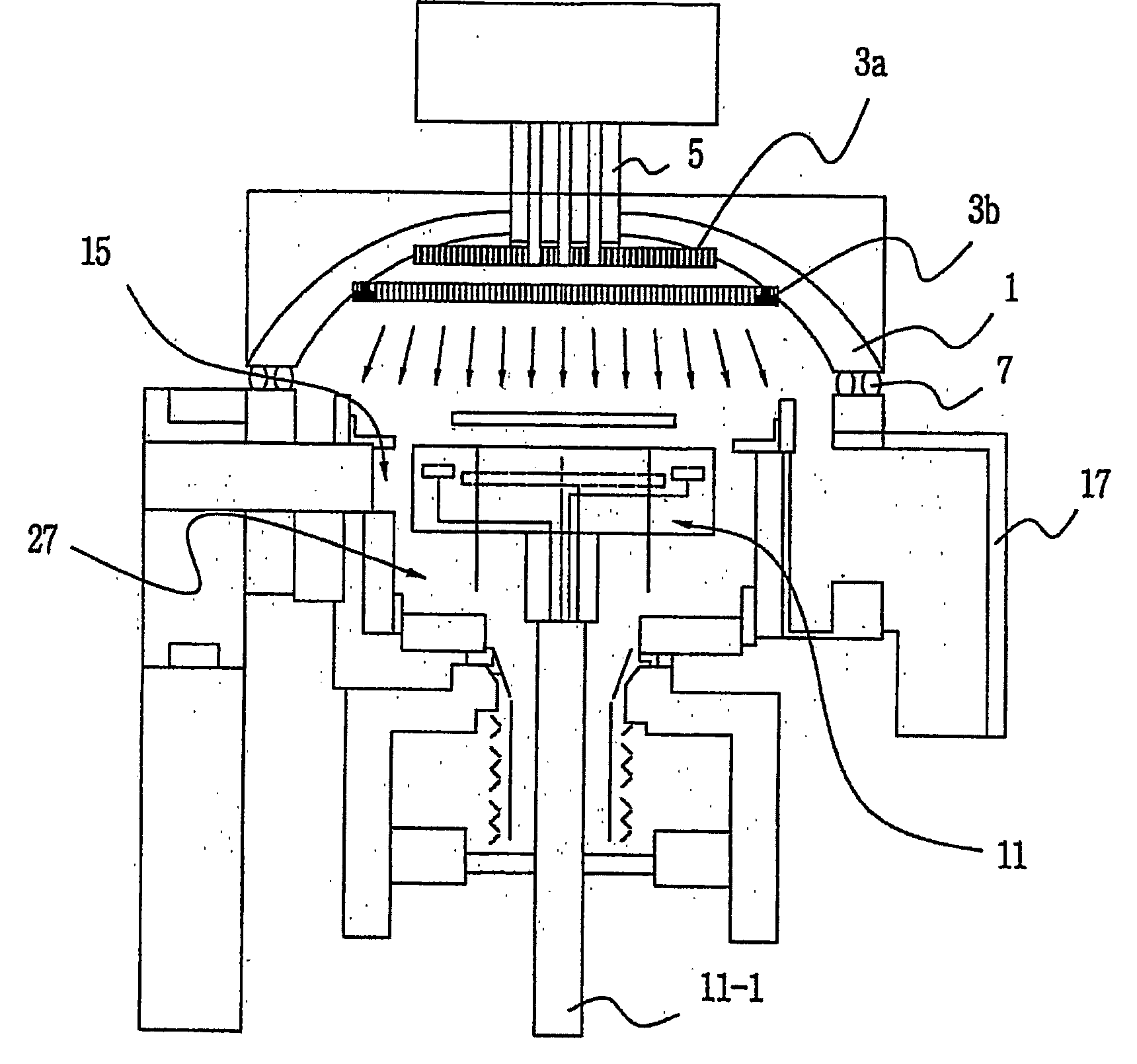
[0026]FIG. 1 is an overall cross-sectional view showing an apparatus for chemical vapor deposition in accordance with a preferred embodiment of the present invention.

[0027] Referring to FIG. 1, the apparatus for chemical vapor deposition comprises an upper chamber, a shower head disposed in the upper chamber, a lower chamber, and a heat source disposed in a defined region of the lower chamber, which components will be described in detail with reference to the following drawings.

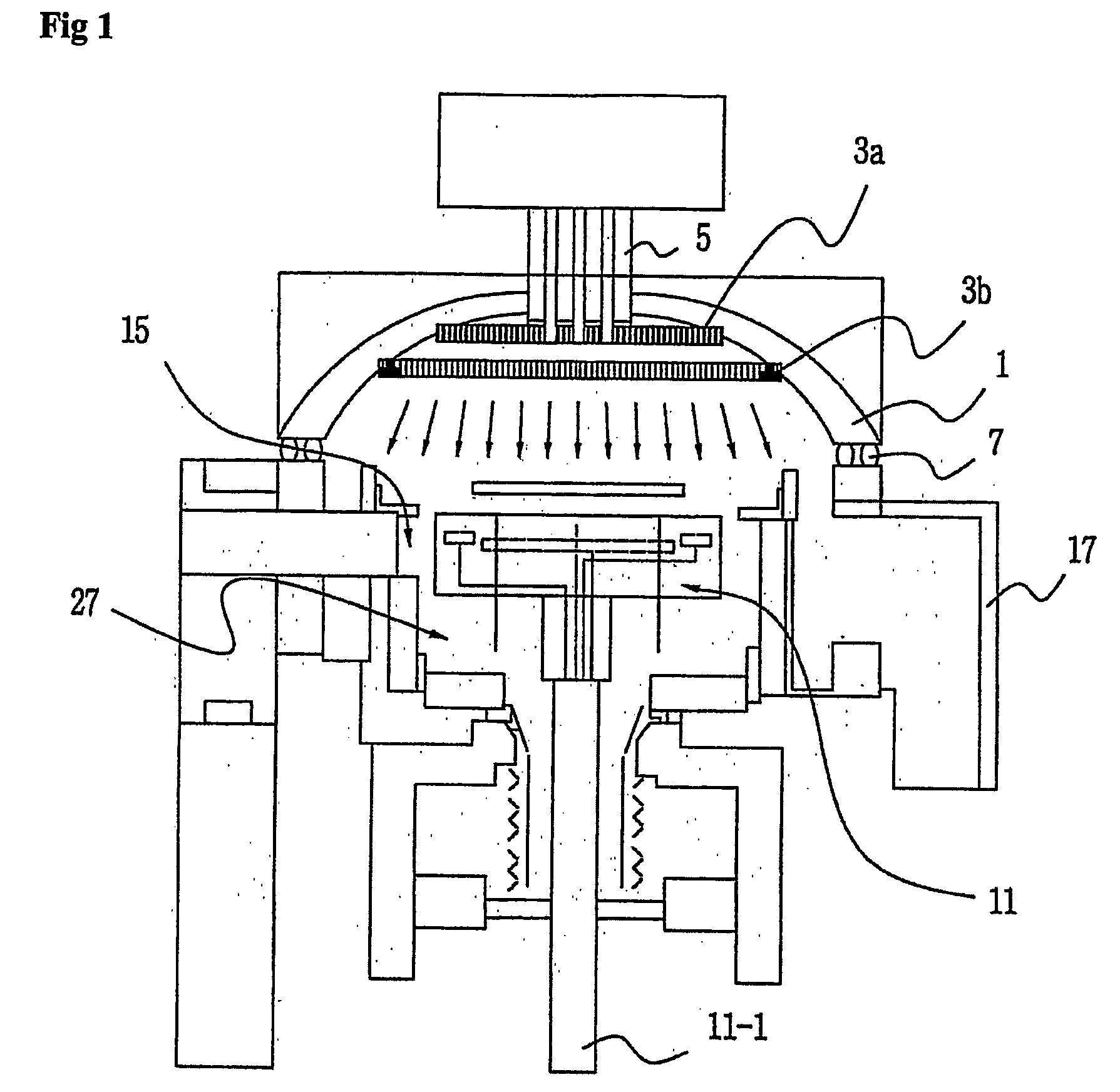
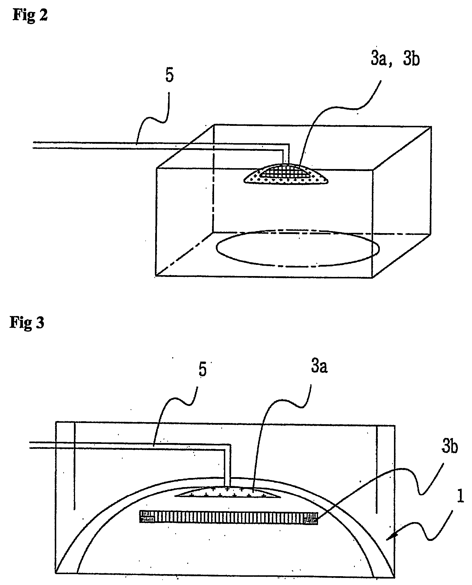
[0028]FIG. 2 is a three-dimensional perspective showing an upper chamber of the apparatus for chemical vapor deposition, FIG. 3 is a cross-sectional view showing the upper chamber of the apparatus for chemical vapor deposition, and FIG. 4 is a bottom plan view showing the upper chamber of the apparatus for chemical vapor deposition.

[0029] Referring to the figures, the upper chamber which has a...


PUM

PropertyMeasurementUnit
Distanceaaaaaaaaaa
Energyaaaaaaaaaa
Vacuumaaaaaaaaaa

Abstract

Disclosed is an apparatus for chemical vapor deposition including: a dome-shaped upper chamber having a half-round surface or a curved surface of a predetermined angle; a shower head disposed in the upper chamber, for ejecting a reaction gas for film deposition straight or radially according to the shape of the upper chamber; a lower chamber sealed off from the upper chamber by way of an O-ring; a heater disposed at the center of the bottom surface of the lower chamber as a heat energy source for forming the films; and a nozzle for ejecting the reaction gas and preventing entrance of the reaction gas from the bottom of the heater. The apparatus ejects the reaction gas for film deposition straight or radially onto the surface of the wafer to secure films excellent in deposition uniformity and remarkably reduce the formation of products in the chamber.

Description

TECHNICAL FIELD [0001] The present invention relates to an apparatus for chemical vapor deposition for depositing films on the surface of a wafer and, more particularly, to an improved apparatus for chemical vapor deposition capable of achieving films excellent in deposition uniformity and minimizing the formation of products in the chamber. BACKGROUND ART [0002] With the tendency of semiconductor devices towards miniaturization with a light weight, the design-rule is greatly reducing and the RC delay designed by wiring has become an important factor that determines the operational speed of the semiconductor devices. Accordingly, the multi-layer wiring structure has been put to practical use. The number of metal wires necessary to the large integrated circuit devices such as microprocessor has increased from two or three to four or six, and more wires will be used with the higher degree of integration of the semiconductor devices in the future. [0003] The wires are usually formed fr...

Claims


Application Information

Patent Timeline
IPC IPC(8): C23C16/44C23C16/455
CPCC23C16/45565C23C16/4401
Inventor UM, PYUNG YONG
Owner EUGENE TECH CO LTD
Why Eureka
Try Eureka