

Sonoelastography using power Doppler
a sonoelastography and power doppler technology, applied in the field of sonoelastography, can solve the problems of power doppler and part of sonoelastography that have not been done befor
- Summary
- Abstract
- Description
- Claims
- Application Information
AI Technical Summary
Benefits of technology
Problems solved by technology
Method used
Image

Examples
Embodiment Construction
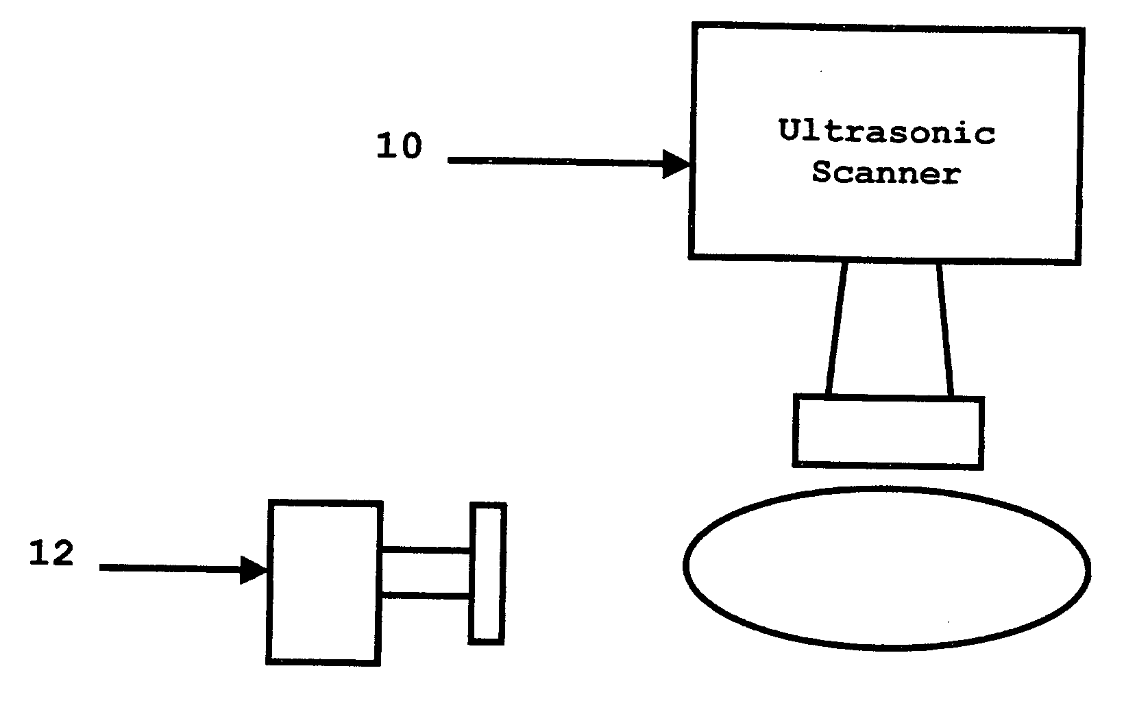
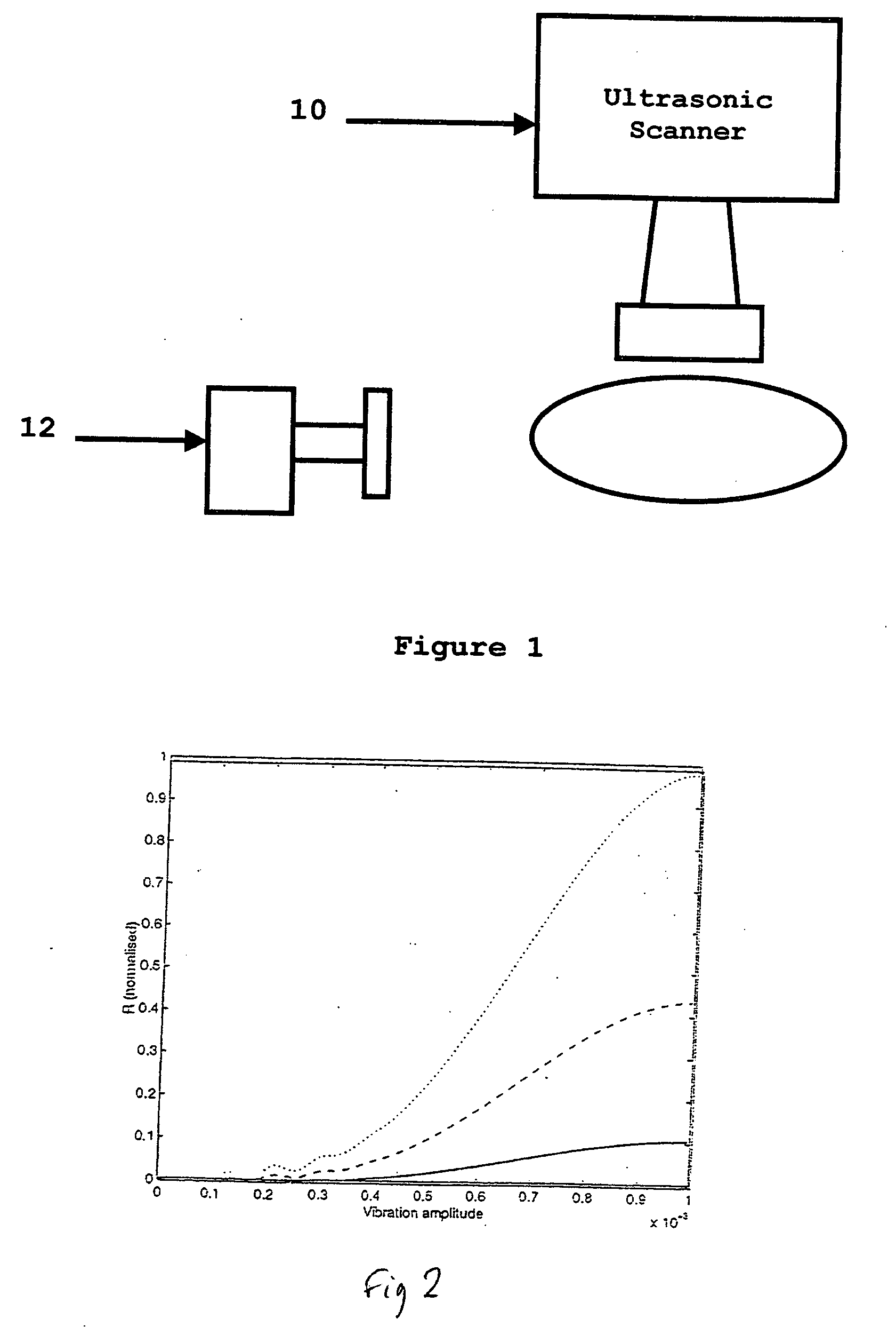
A method in which the present invention is embodied involves vibrating the region of a patient's body that is of interest and capturing a power Doppler image. By doing this, tumors can be detected in a simple, non-invasive manner. It should be noted that power Doppler cannot be used directly to estimate the vibration amplitude because the power Doppler signal depends on the echo strength of the region being imaged as well as its vibration amplitude. However, as a tumor imaging modality, the system is valid because an image that is the product of echo strength and vibration amplitude would be more sensitive for detecting cancer than an image of echo strength alone.
In addition, the method proposed here uses standard B-scan imaging to compensate the power Doppler signal in order to image the relative vibration amplitudes in the tissue. To do this, co-registered B-scan and power Doppler images of the same tissue are captured. This can be done simultaneously or sequentially. Then the B-...
PUM
 Abstract
Description
Claims
Application Information