Cleaning apparatus

a technology for cleaning apparatus and carpet, which is applied in the direction of vacuum cleaners, floor scrubbing machines, carpet cleaners, etc., can solve the problems of affecting the cleaning effect of carpets, etc., and achieves the effect of no toxic emissions

Active Publication Date: 2005-03-17
HYDRAMASTER LLC
View PDF10 Cites 4 Cited by
  • Summary
  • Abstract
  • Description
  • Claims
  • Application Information

AI Technical Summary

Benefits of technology

[0009] Another aspect of the present invention relates to a cleaning apparatus which includes a fluid dispensing tank which dispenses a cleaning fluid which is to be applied to an object of interest; a fluid dispenser coupled in fluid receiving relation relative to the fluid dispensing tank; a heat exchanger disposed downstream of the fluid dispensing tank and upstream of the fluid dispenser, and which is operable to impart heat energy to the fluid moving from the fluid dispensing tank to the fluid dispenser; a catalytic heater disposed in heat transferring relation relative to the heat exchanger; and a fuel supply coupled in fluid flowing relation relative to the catalytic heater, and wherein the combustion of the fuel supply with a source of air by the catalytic heater produces substantially no toxic emissions, and generates heat energy which heats the cleaning fluid dispensed by the fluid dispensing tank.

Problems solved by technology

While devices as exemplified in U.S. Pat. No. 4,803,466 have operated with a great deal of success, there are various shortcomings attendant with these prior art assemblies which have detracted from their usefulness.
More specifically, such devices as exemplified by this, and other U.S. patents, as a general matter, require a large amount of electrical power in order to sufficiently heat the fluids which are to be applied.
Because electrical outlets capable of delivering more than 1800 watts are relatively uncommon in residential and commercial buildings in North America, compromises in temperature rise and / or fluid flow rate must necessarily be made.
Consequently, such devices cannot clean carpets as quickly as could devices that had greater power.
Furthermore, dependence upon electrical cords for power requires an operator of such prior art devices to start and stop these prior art machines several times when the operator is cleaning a given area, such as a floor, in order to move his power cable to the power outlet most near the area where the cleaning machine is operating.
This activity, of course, further slows the progress of cleaning, and also presents inconveniences inasmuch as power cables of the type described often present safety concerns in the form of a tripping hazard for people traveling in the near vicinity of these cleaning machines as they are operating.
In addition to the foregoing, and in some environments, the power cables of such machines may not have a length which will permit such cleaning devices to reach some remote areas.
While cleaning devices having self contained power sources have operated with some degree of success, the useful operational time of such devices is quite limited.
This activity of either on the one hand, recharging the batteries, or replacing the discharged batteries with charged batteries further increases the cost and amount of time necessary to clean a given article or area.
Those skilled in the art will readily recognize that the continuous and repeated deep discharging of rechargeable batteries will typically shorten the life expectancy of such batteries such that they may need to be replaced on a fairly regular timetable.
Still further, machines of this type which have rechargeable batteries which power same are also relatively speaking, large, quite heavy, and difficult to maneuver in small spaces.
Still further, the devices are often difficult to maintain.

Method used


Image

  • Cleaning apparatus
  • Cleaning apparatus
  • Cleaning apparatus

Examples


Embodiment Construction

[0017] This disclosure of the invention is submitted in furtherance of the constitutional purposes of the U.S. Patent Laws “to promote the progress of science and useful arts” (Article 1, Section 8).

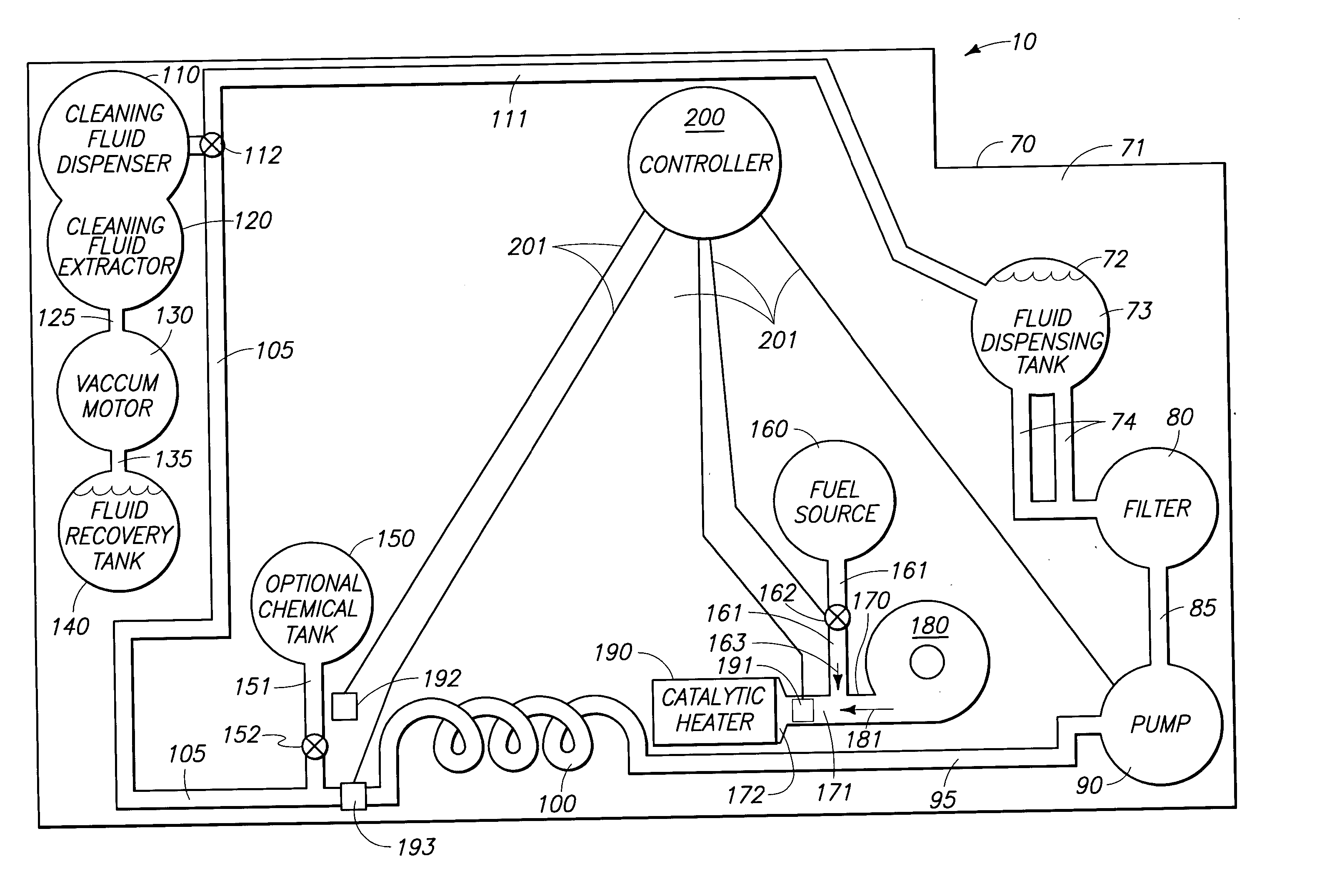
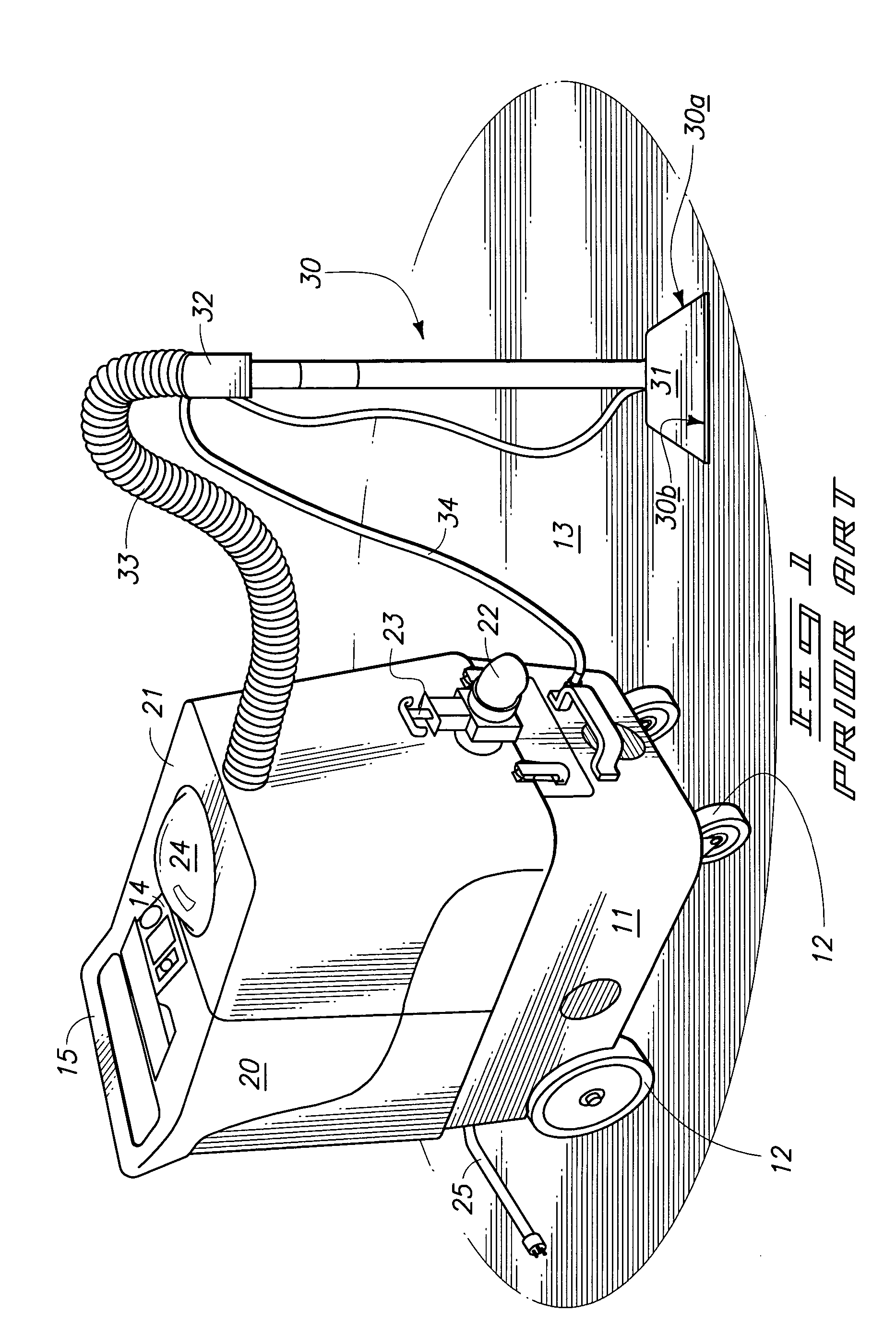
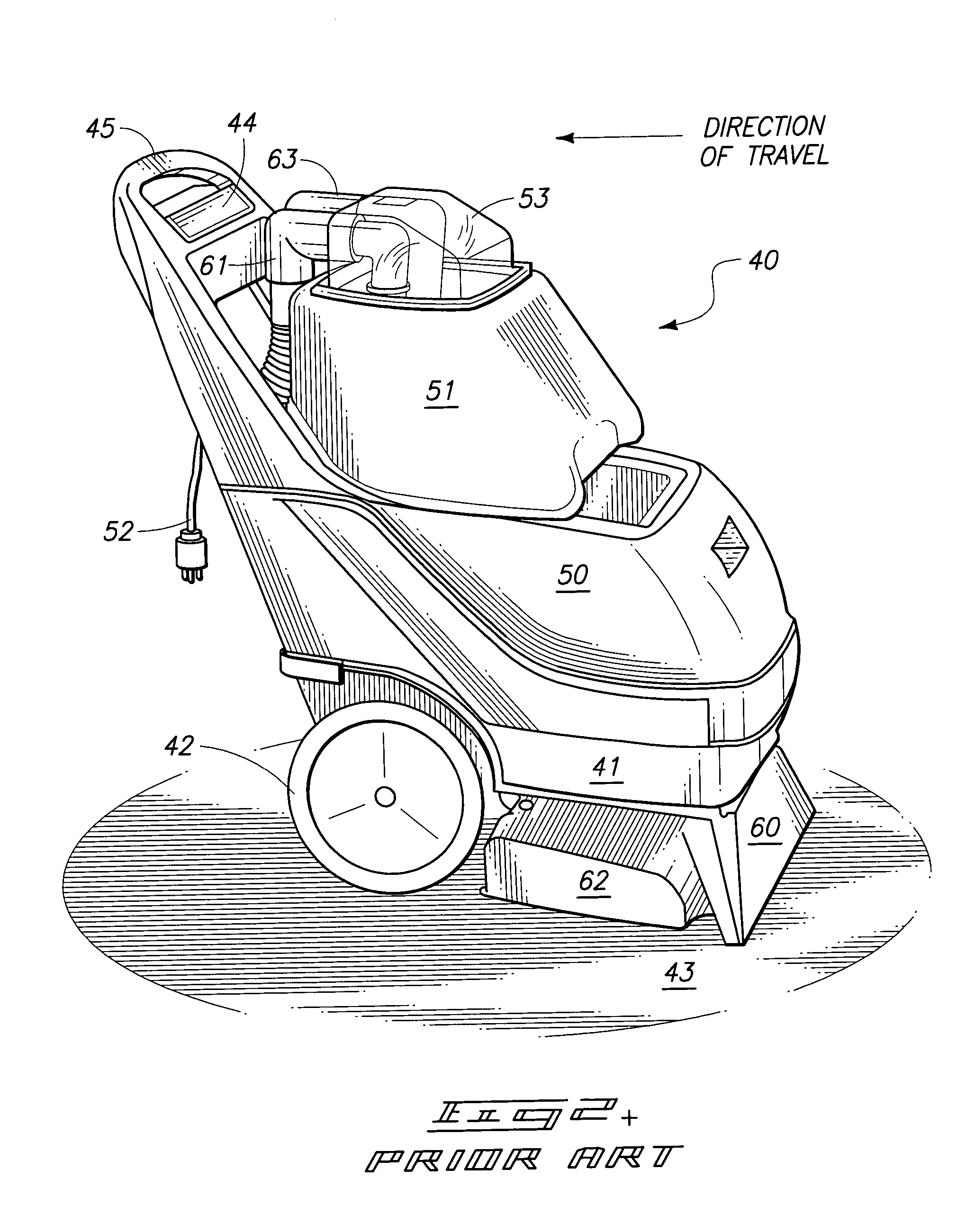
[0018] The cleaning apparatus of the present invention is generally indicated by the numeral 10 in FIG. 3. The features of the invention 10 may be incorporated into various prior art devices such as shown in FIG. 1 and FIG. 2. As should be understood, these cleaning devices may be powered, at least in part, by an AC power source. The teachings of the present invention can also be utilized on prior art devices that have self-contained rechargeable power supplies such as lead-acid batteries. In this regard, it should be understood that utilization of the present invention on a device such as one that has self-contained rechargeable batteries will greatly extend the useful operational time of such assemblies inasmuch as the present invention eliminates a significant amount of the power dra...


PUM


Abstract

A cleaning apparatus is disclosed and which includes a fluid dispensing tank which dispenses a cleaning fluid; a heat exchanger coupled in downstream fluid flowing relation relative to the fluid dispensing tank; a source of a combustible fluid fuel; a source of air; and a catalytic heater positioned in heat transferring relation relative to the heat exchanger, and which further is coupled in fluid flowing relation relative to the combustible fluid fuel, and wherein the catalytic heater catalytically combusts a substantially nonflammable mixture of the combustible fluid fuel and air to produce heat energy which heats the fluid dispensed from the fluid dispensing tank.

Description

TECHNICAL FIELD [0001] The present invention relates to an apparatus for cleaning carpet, upholstery, draperies, and the like, and more specifically to a cleaning apparatus which employs a catalytic heater for heating a fluid which is sprayed onto the surface of carpet, hard floor, upholstery, or draperies and then subsequently removed by suction. BACKGROUND OF THE INVENTION [0002] The prior art includes various types of cleaning devices and other machines which have various types of liquid heating assemblies for heating a cleaning fluid and which is subsequently sprayed onto an object to be cleaned and then suctioned back into a recovery tank. An example of such a prior art device is found in U.S. Pat. No. 4,803,466, the teachings of which are incorporated by reference herein. The device exemplified by the aforementioned patent utilizes an electrical heater which has a corresponding heat exchanger. This assembly heats the fluid to be applied to a given temperature before it is appl...

Claims


Application Information

Patent Timeline
Patent Type & Authority Applications(United States)
IPC IPC(8): A47L11/34
CPCA47L11/34A47L11/4086A47L11/4083A47L11/4011
Inventor HAUFF, DOUGLASWILLIAMS, STEVEFUGLEVAND, WILLIAM A.LLOYD, GREG A.
Owner HYDRAMASTER LLC
Why Eureka
Try Eureka