Corner flashing system

a technology of flashing system and corner, which is applied in the direction of snow traps, building components, roof coverings, etc., can solve the problems of low cost, time-consuming, and inability to meet the needs of use, and achieve the effect of low cos

Active Publication Date: 2005-03-17
SUMMY GENE
View PDF31 Cites 23 Cited by
  • Summary
  • Abstract
  • Description
  • Claims
  • Application Information

AI Technical Summary

Benefits of technology

[0010] The corner flashing system according to the following preferred embodiments has several features, no single one of which is solely responsible for its desirable attributes. Without limiting the scope of this invention as expressed by the claims that follow, its more prominent features will now be discussed briefly. After considering this discussion, and particularly after reading the section entitled “Detailed Description of the Drawings,” one will understand how the features of this flashing system provide advantages, which include reliability, low cost, and foolproof installation.

Problems solved by technology

All of these methods have at least one major drawback.
Some are expensive, some are time consuming, some must be performed just right in order to be effective, some are not durable, and some create sharp edges that cut subsequent layers of building materials.
Recessed windows are particularly difficult to flash and seal adequately, especially at the corners.
Rain, especially wind-driven rain, tends to penetrate the corners of these windows rather easily.
When this water infiltrates the space behind the flashing, it becomes trapped there and causes rotting and deterioration of the underlying wood, as well as fungus, mold and mildew growth within the wall systems.
The inadequacy of current flashing systems is due to two problems.
First, there is no known flashing system that is very reliable, even if installed correctly.
Second, most flashing is performed by unskilled low-wage laborers.
Further, many lack the language skills necessary to understand the detailed instructions that must be given by a supervisor in order to ensure a proper flashing.
Because it is not cost effective to have a supervisor inspect every corner of every recessed window, many windows are installed with poor flashing.
As a result, many flashing systems that might be effective if installed properly every time do not work well in practice.
Therefore, there is a need for a corner flashing system that is not only effective when correctly installed, but is also nearly impossible to install incorrectly.

Method used


Image

  • Corner flashing system
  • Corner flashing system
  • Corner flashing system

Examples


Embodiment Construction

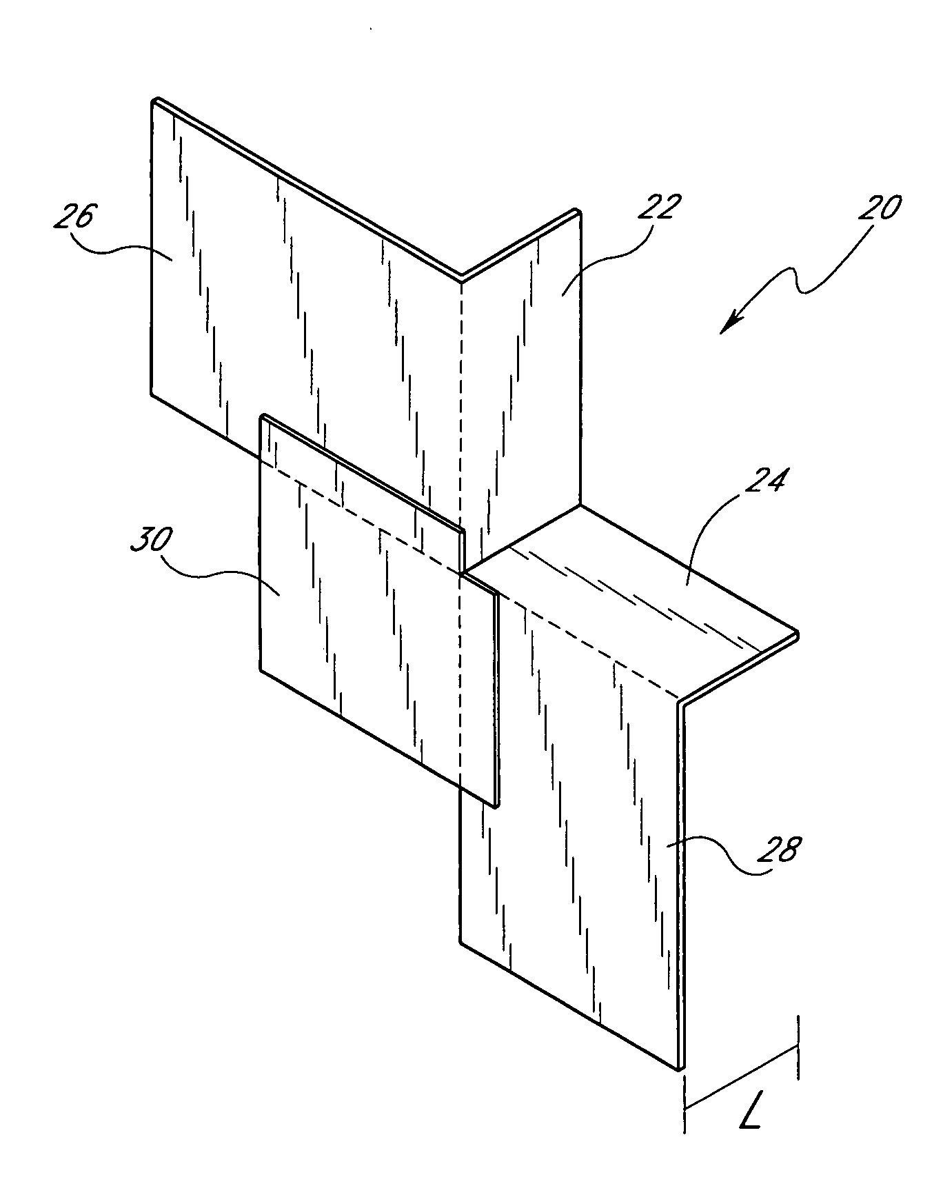
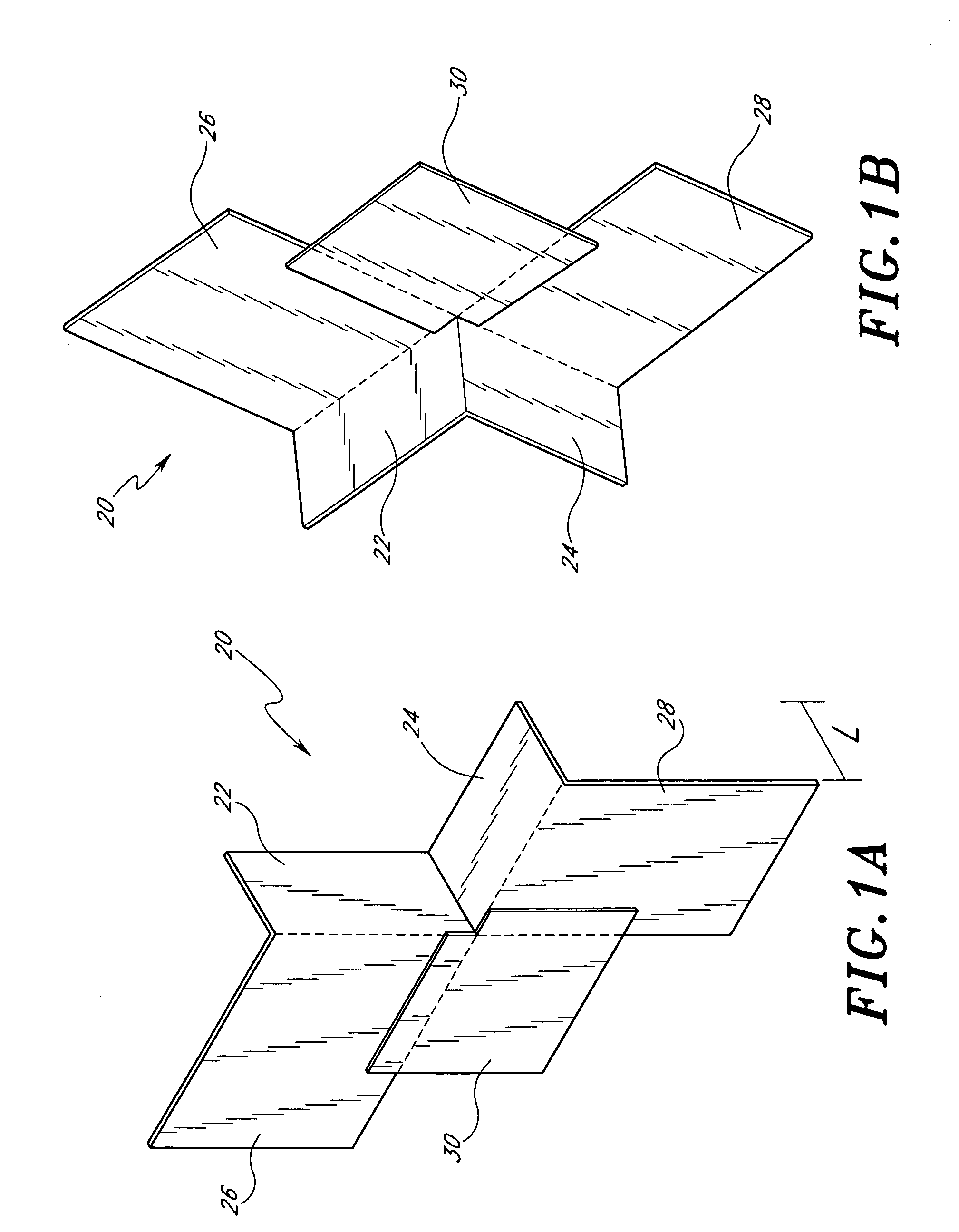
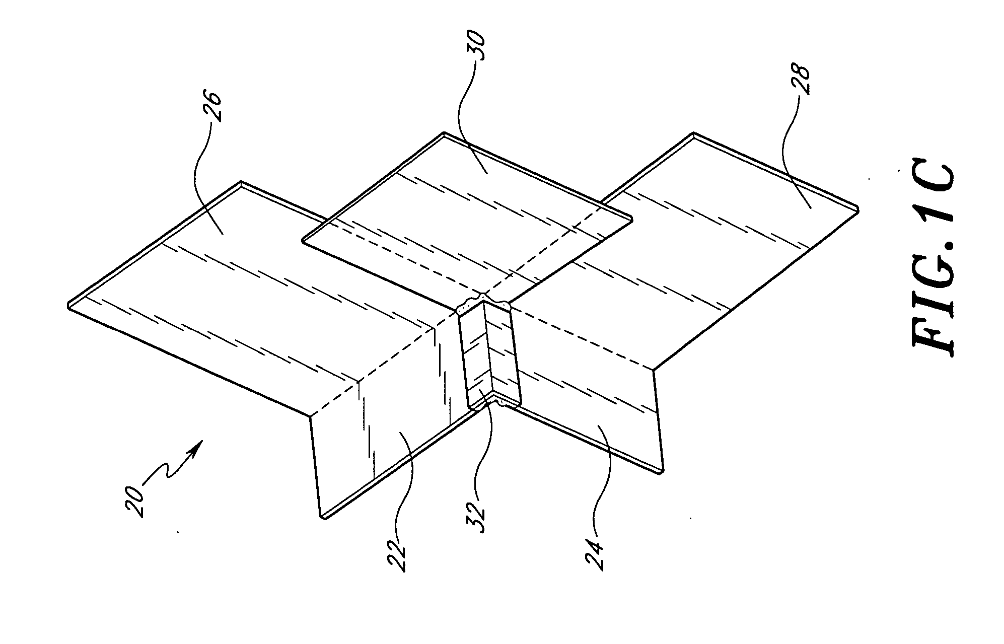
[0037]FIGS. 1A-1B illustrate one preferred embodiment of a double-flap member 20. This member 20 is preferably constructed of an asphalt or petroleum based flashing material, although it will be understood by one skilled in the art that a variety of other materials having water-resistant properties may also be used. This member 20 comprises a vertical seating flange 22 and a horizontal seating flange 24, which are joined at a 90° angle. The vertical flange 22 preferably has substantially the same dimensions as the horizontal flange 24. The length L of the flanges, defined as the direction parallel to both planes defined by the flanges, is appropriate for the dimensions of the structure in which the flanges are installed. Preferred lengths are 1½″, 3⅛″, 12″, 18″, 24″ and 30″. FIG. 1D illustrates a double-flap member 20 having a long dimension L.

[0038] Extending at a 90° angle from one edge of the vertical flange 22 is a substantially rectangular first flap 26. Extending at a 90° ang...


PUM


Abstract

A corner flashing system is provided for sealing the corners of recessed window frames against moisture penetration. In a preferred embodiment, the system comprises first and second double-flap members, a half-cube member, and caulking. The first and second double-flap members, and the half-cube member are preferably made of asphalt or petroleum based material. In another preferred embodiment, the system comprises one double-flap member, a modified half-cube member, and caulking. In another preferred embodiment, the system comprises a single member that combines a double-flap member and a half-cube member, and caulking. In another preferred embodiment, the system comprises a combination member, a double-flap member, and caulking.

Description

RELATED APPLICATIONS [0001] This application is a divisional of copending application Ser. No. 09 / 915,495, filed on Jul. 26, 2001, which claims priority to provisional application Ser. No. 60 / 243,856, filed on Oct. 27, 2000. The entire contents of each of these applications are hereby expressly incorporated by reference.BACKGROUND OF THE INVENTION [0002] 1. Field of the Invention [0003] The present invention relates to systems for providing a water-tight seal at the corners of structures. More specifically, a preferred embodiment provides a device and method for flashing and sealing the corners of recessed window frames and recessed window wall conditions. [0004] 2. Description of the Related Art [0005] In the construction of new homes, it is important to provide a water-tight seal at the seams of any openings in exterior walls, specifically windows and doors. A number of different devices and methods of providing such a seal are in current use. All of these methods have at least on...

Claims


Application Information

Patent Timeline
Patent Type & Authority Applications(United States)
IPC IPC(8): E06B1/62
CPCE06B2001/628E06B1/62
Inventor SUMMY, GENE
Owner SUMMY GENE
Why Eureka
Try Eureka