Building element and structure

Inactive Publication Date: 2005-03-17
ANGLEBLOCK CORP
View PDF5 Cites 7 Cited by
  • Summary
  • Abstract
  • Description
  • Claims
  • Application Information

AI Technical Summary

Benefits of technology

[0007] Another object of the present invention is to provide a dual faced building element wherein one face of the element gives the appearance of a dual vertical octagon shape, and the other face of the element is vertically flat faced, with a 45 degree vertically angled corner on each end of the element, whereby through use of such a design, constructions which have an internal angle of 45, 90 and 135 degrees are possible through manipulating various arrangements of elements with adjacent elements.
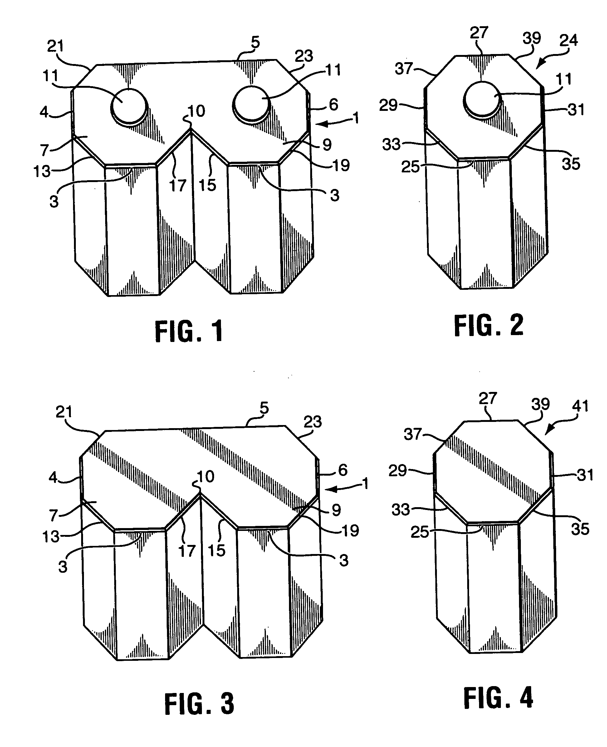
[0009] According to a further aspect of the present invention, there is provided a building element for use in the construction of elevated structures comprising eight sides forming a substantially octagonal shape; a channel formed internally on an underside of the element; and a protrusion projecting from a top surface of the element, the protrusion being dimensioned slightly narrower than a width of the channel and being capable of insertion into a channel of another element, so as to secure the elements together.
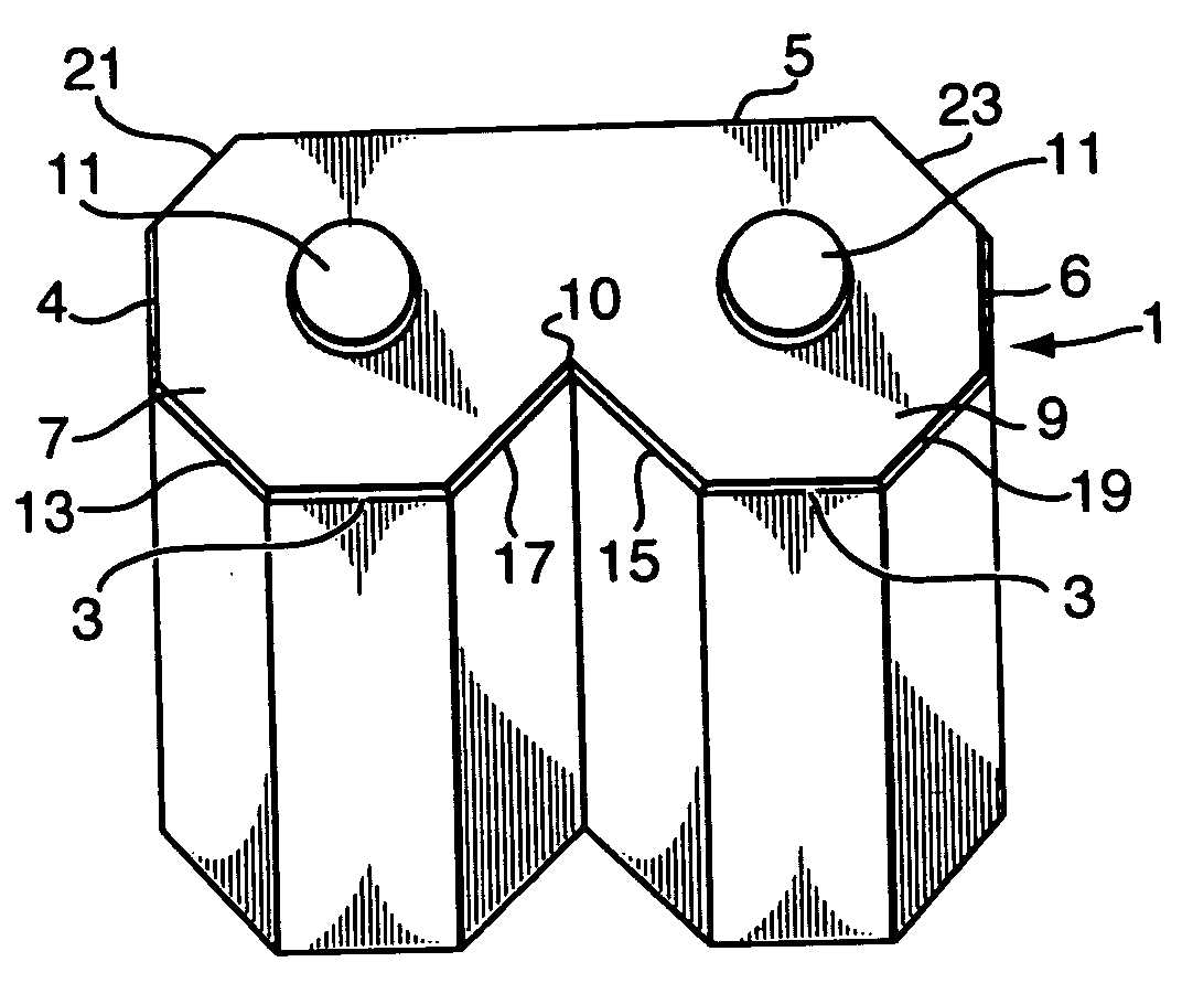
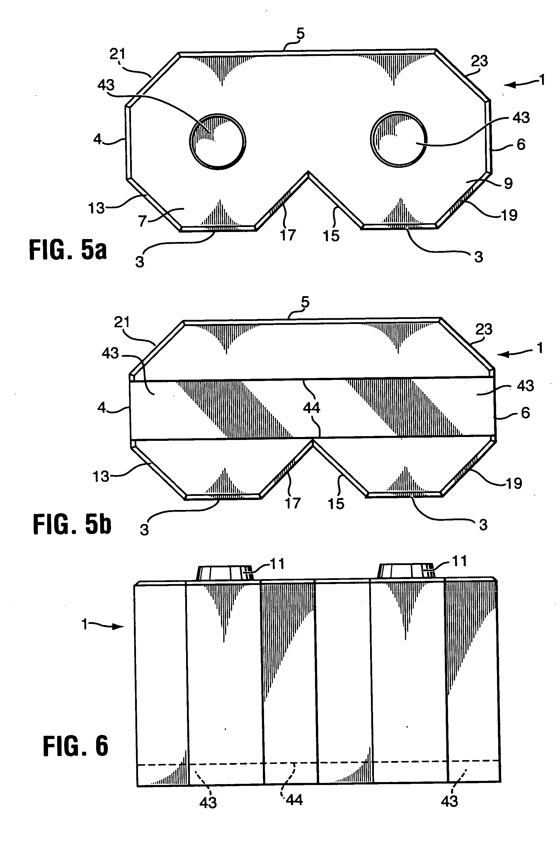
[0015] The building element of the present invention is designed so that either face of the element can be used in the design of the construction of structures, such as retaining walls, wherein one face of the element gives the appearance of a dual vertical octagon shape, and the other face of the element is vertically flat faced, with a 45 degree vertically angled corner on each end of the element. In a construction of this type, essentially, one face of the element does not complete the octagon, rather a flat surface extends the length of the two halves. The primary advantage of this design lies in its versatility. A user may arrange the stone in a variety of fashions which result in a wide ranging finished product, such as a complete wall. Through various configurations of such a design, arrangements of elements to form wall constructions which have an inside or outside corner angle of 45, 90 and 135 degrees are possible. The element can also be used in the design of the construction of a variety of other projects and structures, including posts and foundations.
[0017] In a preferred embodiment of the present invention, there are two protrusions formed on a top surface of each element. Preferably, these protrusions are round and button shaped, however, other configurations and shapes can be utilized as well. The protrusions are designed to allow each element to lock or connect into the groove or channel on the underside of another element placed thereon. In this manner, building elements comprising the elevated structure can be stacked straight up in forming a complete elevated structure, and increases the strength and durability of the structure.
[0019] Though generally speaking it is preferable for an elevated structure constructed with the elements of the present invention to feature full size elements wherein one face provides the dual vertical octagon shape, and the other face of the element is vertically flat faced, nevertheless, in a further embodiment of the present invention a “half” element may also be used in designing the elevated structure and giving it a unique appearance. The entire outer periphery of the “half” element comprises an octagonal shape, and possesses a channel formed internally on an underside of the element, with a corresponding singular protrusion also projecting from a top surface of the element. By utilizing a “half” element in constructing an elevated structure, in combination with the regular sized element of the present invention, it is possible to place singular “half elements” on top of a singular protrusion of a regular sized element at staggered, spaced intervals in the elevated structure construction. When, in assembling the elevated structure, full sized elements of the present invention are then further locked or connected on the protrusion of the “half” element, the result is an elevated structure construction which, depending upon the interval between placement of the “half elements”, can provide for gaps in the outer surface of the structure, which enables an aesthetically appealing, unique configuration.

Problems solved by technology

However, use of these types of blocks for the construction of retaining wall structures are generally not aesthetically appealing.
However, this technique is very time consuming in that it requires a skilled mason to cut each and every block at the desired angle.
However these types of blocks do not provide for a unique appearance and configuration with respect to the corners incorporated into the retaining wall.

Method used


Image

  • Building element and structure
  • Building element and structure
  • Building element and structure

Examples


Embodiment Construction

[0043] Referring to FIG. 1, there is shown a perspective view of a retaining wall unit of the present invention. The retaining wall element (1) comprises a front side (3) for each of the first (7) and second halved (9) portions. A substantially planar rear side (5) extends a total length of the first (7) and second halved (9) portions. The retaining wall element also possesses a left side (4) and a right side (6). A channel (not shown) is also formed internally on an underside of each of the halved portions (7,9) of the wall element (1), and a protrusion (11) projects from a top surface of each of the halved portions (7,9) of the wall element (1). Each of the halved portions (7,9) further comprise first and second diagonal sides, the first diagonal side (13) of the first halved portion (7) being disposed between the front side (3) and the left side (4), and the first diagonal side (15) of the second halved portion (9) also being disposed between the front side (3) and the left side ...


PUM


Abstract

A precast concrete building element and structure constructed from such elements, the elements being designed so that either face of the element can be used in the design of the construction of retaining walls, foundations, posts or other structures, wherein one face of the element gives the appearance of a dual vertical octagon shape, and the other face of the element is vertically flat faced, with a 45 degree vertically angled corner on each end of the element. Thus, the overall wall or structure gives the appearance of repeating vertical part octagonal shapes. Through various configurations of such a design, arrangements of elements to form structures which have an internal angle of 45, 90 and 135 degrees are possible. The structure can be designed so that it can be stacked straight up, in that each element comprising the structure has a groove or channel on a bottom of the element, which internally extends a length of the element, and a top surface of the element has two button shaped protrusions thereon. The protrusions are designed to allow each element to lock or connect into the groove or channel of another element placed thereon.

Description

FIELD OF THE INVENTION [0001] The present invention relates to a precast concrete building element and structure constructed from such element. In particular, this invention relates to a dual faced retaining element which has been designed so that either face can be used in the design of the construction of retaining walls, wherein one face of the wall element gives the appearance of a dual vertical octagon shape, and the other face of the wall element is vertically flat faced, with a 45 degree vertically angled corner on each end of the wall element. Through use of such a design, wall constructions which have an inside or outside angle of 45, 90 and 135 degrees are possible. The element can also be used in the design of the construction of a variety of other projects and structures, including foundations, posts and other configurations. BACKGROUND OF THE INVENTION [0002] Retaining wall blocks and walls, for example, are used in various landscaping projects and are generally availab...

Claims


Application Information

Patent Timeline
IPC IPC(8): E02D29/02E04B2/02E04C1/39
CPCE02D29/025E04C1/395E04B2002/0263E04B2002/0221
Inventor MUISE, THOMAS
Owner ANGLEBLOCK CORP
Why Eureka
Try Eureka